Sometimes, you need to be able to constrain a type-parameter with a method, but
that method should be defined on the pointer type. For example, say you want to
parse some bytes using JSON and pass the result to a handler. You might try
to write this as
However, this code does not work. Say you have a type Message, which
implements json.Unmarshaler with a pointer receiver (it needs to use a
pointer receiver, as it needs to be able to modify data):
If you try to call Handle[Message], you get a compiler error
(playground).
That is because Message does not implement json.Unmarshal, only
*Message does.
If you try to call Handle[*Message], the code panics
(playground),
because var m M creates a *Message and initializes that to nil. You
then call UnmarshalJSON with a nil receiver.
Neither of these options work. You really want to rewrite Handle, so that it
says that the pointer to its type parameter implements json.Unmarshaler.
And this is how to do that (playground):
typeUnmarshaler[Many]interface{*Mjson.Unmarshaler}funcHandle[Many,PMUnmarshaler[M]](b[]byte,handlerfunc(M)error)error{varmM// note: you need PM(&m), as the compiler can not infer (yet) that you can
// call the method of PM on a pointer to M.
iferr:=PM(&m).UnmarshalJSON(b);err!=nil{returnerr}returnhandler(m)}
I maintain two builds of the Linux kernel, a linux/arm64 build for gokrazy,
my Go appliance platform, which started out on the
Raspberry Pi, and then a linux/amd64 one for router7,
which runs on PCs.
The update process for both of these builds is entirely automated, meaning new
Linux kernel releases are automatically tested and merged, but recently the
continuous integration testing failed to automatically merge Linux
6․7 — this article is about tracking
down the root cause of that failure.
Background info on the bootloader
gokrazy started out targeting only the Raspberry Pi, where you configure the
bootloader with a plain text file on a FAT partition, so we did not need to
include our own UEFI/MBR bootloader.
When I ported gokrazy to work on PCs in BIOS mode, I decided against complicated
solutions like GRUB — I really wasn’t looking to maintain a GRUB package. Just
keeping GRUB installations working on my machines is enough work. The fact that
GRUB consists of many different files (modules) that can go out of sync really
does not appeal to me.
Instead, I went with Sebastian Plotz’s Minimal Linux
Bootloader because it fits
entirely into the Master Boot Record
(MBR) and does not require
any files. In bootloader lingo, this is a stage1-only bootloader. You don’t even
need a C compiler to compile its (Assembly) code. It seemed simple enough to
integrate: just write the bootloader code into the first sector of the gokrazy
disk image; done. The bootloader had its last release in 2012, so no need for
updates or maintenance.
You can’t really implement booting a kernel and parsing text configuration
files in 446
bytes of 16-bit
8086 assembly instructions, so to tell the bootloader where on disk to load the
kernel code and kernel command line from, gokrazy writes the disk offset
(LBA) of vmlinuz and
cmdline.txt to the last bytes of the bootloader code. Because gokrazy
generates the FAT partition, we know there is never any fragmentation, so the
bootloader does not need to understand the FAT file system.
Symptom
The symptom was that the rtr7/kernelpull request
#434 for updating to Linux 6.7 failed.
My continuous integration tests run in two environments: a physical embedded PC
from PC Engines (apu2c4) in my living room, and a
virtual QEMU PC. Only the QEMU test failed.
On the physical PC Engines apu2c4, the pull request actually passed the boot
test. It would be wrong to draw conclusions like “the issue only affects QEMU”
from this, though, as later attempts to power on the apu2c4 showed the device
boot-looping. I made a mental note that something is different about how the
problem affects the two environments, but both are affected, and decided to
address the failure in QEMU first, then think about the PC Engines failure some
more.
In QEMU, the output I see is:
SeaBIOS (version Arch Linux 1.16.3-1-1)

iPXE (http://ipxe.org) 00:03.0 C900 PCI2.10 PnP PMM+06FD3360+06F33360 C900

Booting from Hard Disk...
Booting from Hard Disk...
Booting from 0000:7c00
In resume (status=0)
In 32bit resume
Attempting a hard reboot
This doesn’t tell me anything unfortunately.
Okay, so something about introducing Linux 6.7 into my setup breaks MBR boot.
I figured using Git Bisection
should identify the problematic change within a few iterations, so I cloned the
currently working Linux 6.6 source code, applied the router7 config and compiled
it.
To my surprise, even my self-built Linux 6.6 kernel would not boot! 😲
Why does the router7 build work when built inside the Docker container, but not
when built on my Linux installation? I decided to rebase the Docker container
from Debian 10 (buster, from 2019) to Debian 12 (bookworm, from 2023) and that
resulted in a non-booting kernel, too!
We have two triggers: building Linux 6.7 or building older Linux, but in newer
environments.
Meta: Following Along
(Contains spoilers) Instructions for following along
First, check out the rtr7/kernel repository and undo the mitigation:
% mkdir -p go/src/github.com/rtr7/
% cd go/src/github.com/rtr7/
% git clone --depth=1 https://github.com/rtr7/kernel
% cd kernel
% sed -i 's,CONFIG_KERNEL_ZSTD,#CONFIG_KERNEL_ZSTD,g' cmd/rtr7-build-kernel/config.addendum.txt
% go run ./cmd/rtr7-rebuild-kernel
# takes a few minutes to compile Linux
% ls -l vmlinuz
-rw-r--r-- 1 michael michael 15885312 2024-01-28 16:18 vmlinuz
Now, you can either create a new gokrazy instance, replace the kernel and
configure the gokrazy instance to use rtr7/kernel:
Unlike application programs, the Linux kernel doesn’t depend on shared libraries
at runtime, so the dependency footprint is a little smaller than usual. The most
significant dependencies are the components of the build environment, like the C
compiler or the linker.
So let’s look at the software versions of the known-working (Debian 10)
environment and the smallest change we can make to that (upgrading to Debian
11):
Debian 10 (buster) contains gcc-8 (8.3.0-6) and binutils 2.31.1-16.
Debian 11 (bullseye) contains gcc-10 (10.2.1-6) and binutils 2.35.2-2.
To figure out if the problem is triggered by GCC, binutils, or something else
entirely, I checked:
Debian 10 (buster) with its gcc-8, but with binutils 2.35 from bullseye
still works. (Checked by updating /etc/apt/sources.list, then upgrading only
the binutils package.)
Debian 10 (buster), but with gcc-10 and binutils 2.35 results in a
non-booting kernel.
So it seems like upgrading from GCC 8 to GCC 10 triggers the issue.
Instead of working with a Docker container and Debian’s packages, you could also
use Nix. The instructions
aren’t easy, but I used
nix-shell
to quickly try out GCC 8 (works), GCC 9 (works) and GCC 10 (kernel doesn’t boot)
on my machine.
New Hypothesis
To recap, we have two triggers: building Linux 6.7 or building older Linux, but
with GCC 10.
Two theories seemed most plausible to me at this point: Either a change in GCC
10 (possibly enabled by another change in Linux 6.7) is the problem, or the size
of the kernel is the problem.
To verify the file size hypothesis, I padded a known-working vmlinuz file to
the size of a known-broken vmlinuz:
Indeed, building the kernel with Debian 11 (bullseye), but with
CONFIG_STACKPROTECTOR=n makes it boot. So, I suspected that our bootloader
does not set up the stack correctly, or similar.
I sent an email to Sebastian Plotz, the author of the Minimal Linux Bootloader,
to ask if he knew about any issues with his bootloader, or if stack protection
seems like a likely issue with his bootloader to him.
To my surprise (it has been over 10 years since he published the bootloader!) he
actually replied: He hadn’t received any problem reports regarding his
bootloader, but didn’t really understand how stack protection would be related.
Debugging with QEMU
At this point, we have isolated at least one trigger for the problem, and
exhausted the easy techniques of upgrading/downgrading surrounding software
versions and asking upstream.
It’s time for a Tooling Level Up! Without a debugger you can only poke into
the dark, which takes time and doesn’t result in thorough
explanations. Particularly in this case, I think it is very likely that any
source modifications could have introduced subtle issues. So let’s reach for a
debugger!
Luckily, QEMU comes with built-in support for the GDB debugger. Just add the -s -S flags to your QEMU command to make QEMU stop execution (-s) and set up a
GDB stub (-S) listening on localhost:1234.
If you wanted to debug the Linux kernel, you could connect GDB to QEMU right
away, but for debugging a boot loader we need an extra step, because the boot
loader runs in Real Mode, but QEMU’s
GDB integration rightfully defaults to the more modern Protected Mode.
When GDB is not configured correctly, it decodes addresses and registers with
the wrong size, which throws off the entire disassembly — compare GDB’s
output with our assembly source:
On the web, people are working around this bug by using a modified target.xml
file. I
tried this, but must have made a mistake — I thought modifying target.xml
didn’t help, but when I wrote this article, I found that it does actually seem
to work. Maybe I didn’t use qemu-system-i386 but the x86_64 variant or
something like that.
Using an older QEMU
It is typically an exercise in frustration to get older software to compile in newer environments.
It’s much easier to use an older environment to run old software.
Unfortunately, the oldest listed version (QEMU 3.1 in Debian 10 (buster)) isn’t
old enough. By querying snapshot.debian.org, we can see that Debian 9
(stretch) contained QEMU
2.8.
So let’s run Debian 9 — the easiest way I know is to use Docker:
% docker run --net=host -v /tmp:/tmp -ti debian:stretch
Unfortunately, the debian:stretch Docker container does not work out of the
box anymore, because its /etc/apt/sources.list points to the deb.debian.org
CDN, which only serves current versions and no longer serves stretch.
So we need to update the sources.list file to point to
archive.debian.org. To correctly install QEMU you need both entries, the
debian line and the debian-security line, because the Docker container has
packages from debian-security installed and gets confused when these are
missing from the package list:
root@650a2157f663:/# cat > /etc/apt/sources.list <<'EOT'
deb http://archive.debian.org/debian/ stretch contrib main non-free
deb http://archive.debian.org/debian-security/ stretch/updates main
EOT
root@650a2157f663:/# apt update
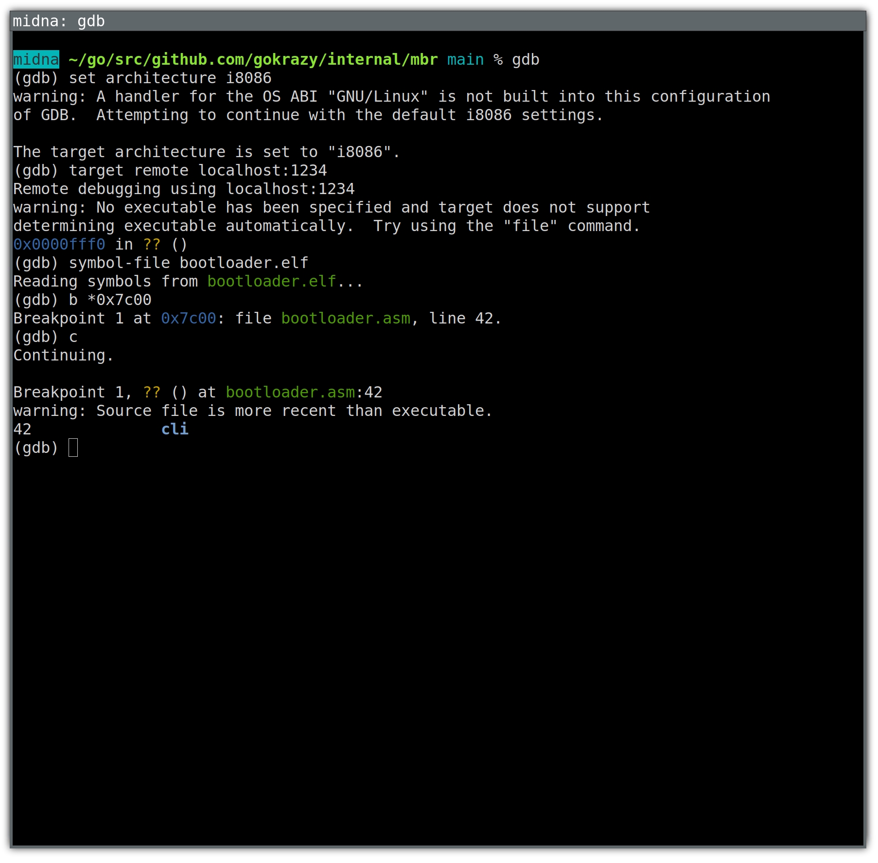
Now we can just install QEMU as usual and start it to debug our boot process:
% gdb
(gdb) set architecture i8086
The target architecture is set to "i8086".
(gdb) target remote localhost:1234
Remote debugging using localhost:1234
0x0000fff0 in ?? ()
(gdb) break *0x7c00
Breakpoint 1 at 0x7c00
(gdb) continue
Continuing.

Breakpoint 1, 0x00007c00 in ?? ()
(gdb)
Debug symbols
Okay, so we have GDB attached to QEMU and can step through assembly
instructions. Let’s start debugging!?
Not so fast. There is another Tooling Level Up we need first: debug
symbols. Yes, even for a Minimal Linux Bootloader, which doesn’t use any
libraries or local variables. Having proper names for functions, as well as line
numbers, will be hugely helpful in just a second.
Before debug symbols, I would directly build the bootloader using nasm bootloader.asm, but to end up with a symbol file for GDB, we need to instruct
nasm to generate an ELF file with debug symbols, then use ld to link it and
finally use objcopy to copy the code out of the ELF file again.
After commit
d29c615
in gokrazy/internal/mbr, I have bootloader.elf.
Back in GDB, we can load the symbols using the symbol-file command:
(gdb) set architecture i8086
The target architecture is set to "i8086".
(gdb) target remote localhost:1234
Remote debugging using localhost:1234
0x0000fff0 in ?? ()
(gdb) symbol-file bootloader.elf
Reading symbols from bootloader.elf...
(gdb) break *0x7c00
Breakpoint 1 at 0x7c00: file bootloader.asm, line 48.
(gdb) continue
Continuing.

Breakpoint 1, ?? () at bootloader.asm:48
48		cli
(gdb)
Automation with .gdbinit
At this point, we need 4 commands each time we start GDB. We can automate these
by writing them to a .gdbinit file:
% cat > .gdbinit <<'EOT'
set architecture i8086
target remote localhost:1234
symbol-file bootloader.elf
break *0x7c00
EOT

% gdb
The target architecture is set to "i8086".
0x0000fff0 in ?? ()
Breakpoint 1 at 0x7c00: file bootloader.asm, line 48.
(gdb)
Understanding program flow
The easiest way to understand program flow seems to be to step through the program.
But Minimal Linux Bootloader (MLB) contains loops that run through thousands of
iterations. You can’t use gdb’s stepi command with that.
Because MLB only contains a few functions, I eventually realized that placing a
breakpoint on each function would be the quickest way to understand the
high-level program flow:
(gdb) b read_kernel_setup
Breakpoint 2 at 0x7c38: file bootloader.asm, line 75.
(gdb) b check_version
Breakpoint 3 at 0x7c56: file bootloader.asm, line 88.
(gdb) b read_protected_mode_kernel
Breakpoint 4 at 0x7c8f: file bootloader.asm, line 105.
(gdb) b read_protected_mode_kernel_2
Breakpoint 5 at 0x7cd6: file bootloader.asm, line 126.
(gdb) b run_kernel
Breakpoint 6 at 0x7cff: file bootloader.asm, line 142.
(gdb) b error
Breakpoint 7 at 0x7d51: file bootloader.asm, line 190.
(gdb) b reboot
Breakpoint 8 at 0x7d62: file bootloader.asm, line 204.
With the working kernel, we get the following transcript:
(gdb)
Continuing.

Breakpoint 2, read_kernel_setup () at bootloader.asm:75
75		xor	eax, eax
(gdb)
Continuing.

Breakpoint 3, check_version () at bootloader.asm:88
88		cmp	word [es:0x206], 0x204		; we need protocol version >= 2.04
(gdb)
Continuing.

Breakpoint 4, read_protected_mode_kernel () at bootloader.asm:105
105		mov	edx, [es:0x1f4]			; edx stores the number of bytes to load
(gdb)
Continuing.

Breakpoint 5, read_protected_mode_kernel_2 () at bootloader.asm:126
126		mov	eax, edx
(gdb)
Continuing.

Breakpoint 6, run_kernel () at bootloader.asm:142
142		cli
(gdb)
With the non-booting kernel, we get:
(gdb) c
Continuing.

Breakpoint 1, ?? () at bootloader.asm:48
48		cli
(gdb)
Continuing.

Breakpoint 2, read_kernel_setup () at bootloader.asm:75
75		xor	eax, eax
(gdb)
Continuing.

Breakpoint 3, check_version () at bootloader.asm:88
88		cmp	word [es:0x206], 0x204		; we need protocol version >= 2.04
(gdb)
Continuing.

Breakpoint 4, read_protected_mode_kernel () at bootloader.asm:105
105		mov	edx, [es:0x1f4]			; edx stores the number of bytes to load
(gdb)
Continuing.

Breakpoint 1, ?? () at bootloader.asm:48
48		cli
(gdb)
Okay! Now we see that the bootloader starts loading the kernel from disk into
RAM, but doesn’t actually get far enough to call run_kernel, meaning the
problem isn’t with stack protection, with loading a working command line or with
anything inside the Linux kernel.
This lets us rule out a large part of the problem space. We now know that we can
focus entirely on the bootloader and why it cannot load the Linux kernel into
memory.
Let’s take a closer look…
Wait, this isn’t GDB!
In the example above, using breakpoints was sufficient to narrow down the problem.
You might think we used GDB, and it looked like this:
But that’s not GDB! It’s an easy mistake to make. After all, GDB starts up with
just a text prompt, and as you can see from the example above, we can just enter
text and achieve a good result.
To see the real GDB, you need to start it up fully, meaning including its user
interface.
You can either use GDB’s text user interface (TUI), or a graphical user
interface for gdb, such as the one available in Emacs.
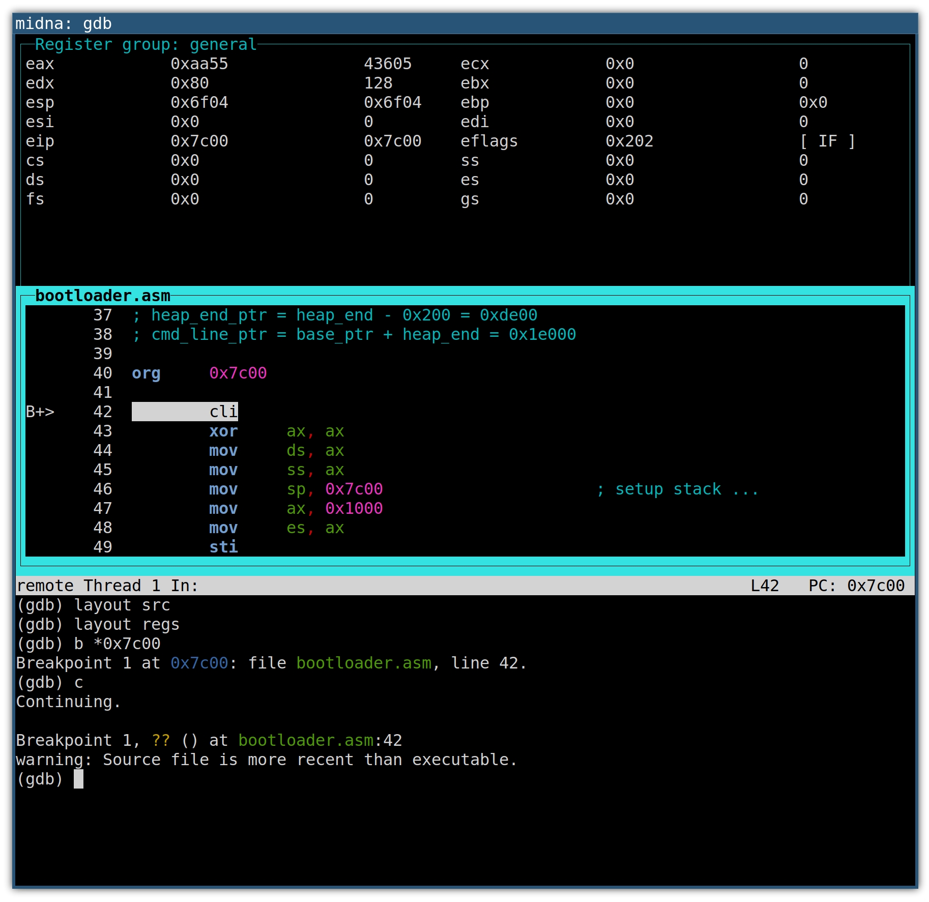
The GDB text-mode user interface (TUI)
You’re already familiar with the architecture, target and breakpoint
commands from above. To also set up the text-mode user interface, we run a few
layout commands:
The layout split command loads the text-mode user interface and splits the
screen into a register window, disassembly window and command window.
With layout src we disregard the disassembly window in favor of a source
listing window. Both are in assembly language in our case, but the source
listing contains comments as well.
The layout src command also got rid of the register window, which we’ll get
back using layout regs. I’m not sure if there’s an easier way.
The result looks like this:
The source window will highlight the next line of code that will be executed. On
the left, the B+ marker indicates an enabled breakpoint, which will become
helpful with multiple breakpoints. Whenever a register value changes, the
register and its new value will be highlighted.
The up and down arrow keys scroll the source window.
Use C-x o to switch between the windows.
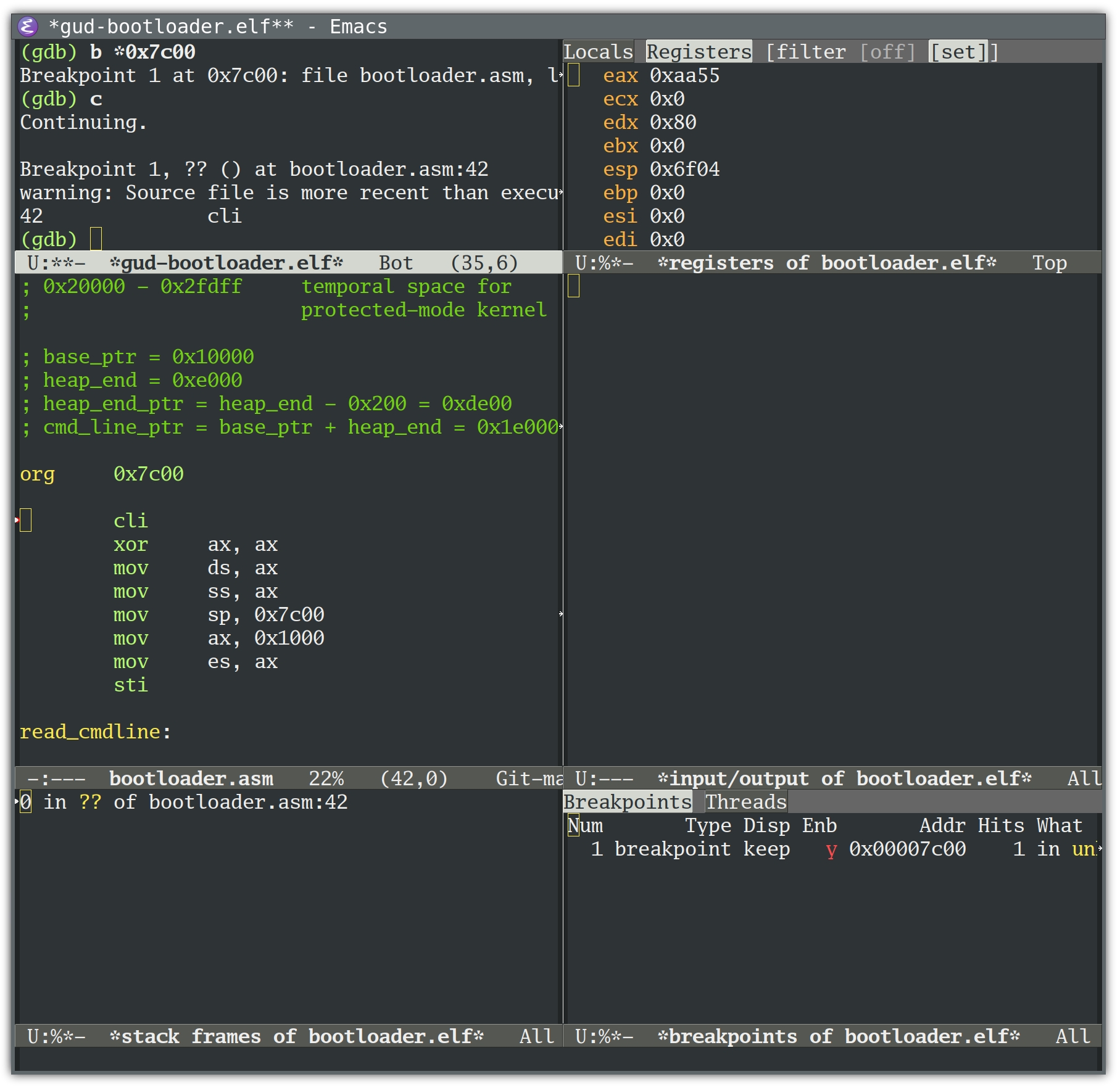
If you’re familiar with Emacs, you’ll recognize the keyboard shortcut. But as an
Emacs user, you might prefer the GDB Emacs user interface:
Let’s take a look at the loop that we know the bootloader is entering, but not
leaving (neither read_protected_mode_kernel_2 nor run_kernel are ever called):
read_protected_mode_kernel:movedx, [es:0x1f4] ; edx stores the number of bytes to load
shledx, 4.loop:cmpedx, 0jerun_kernelcmpedx, 0xfe00; less than 127*512 bytes remaining?
jbread_protected_mode_kernel_2moveax, 0x7f; load 127 sectors (maximum)
xorbx, bx; no offset
movcx, 0x2000; load temporary to 0x20000
movesi, current_lbacallread_from_hddmovcx, 0x7f00; move 65024 bytes (127*512 byte)
calldo_movesubedx, 0xfe00; update the number of bytes to load
addword [gdt.dest], 0xfe00adcbyte [gdt.dest+2], 0jmpshortread_protected_mode_kernel.loop
The comments explain that the code loads chunks of FE00h == 65024 (127*512)
bytes at a time.
Loading means calling read_from_hdd, then do_move. Let’s take a look at do_move:
do_move:pushedxpushesxorax, axmoves, axmovah, 0x87movsi, gdtint0x15; line 182
jcerrorpopespopedxret
int 0x15 is a call to the BIOS Service Interrupt, which will dispatch the call
based on AH == 87H to the Move Memory Block
(techhelpmanual.com)
function.
This function moves the specified amount of memory (65024 bytes in our case)
from source/destination addresses specified in a Global Descriptor Table (GDT)
record.
We can use GDB to show the addresses of each of do_move’s memory move calls by
telling it to stop at line 182 (the int 0x15 instruction) and print the GDT
record’s destination descriptor:
(gdb) break 182
Breakpoint 2 at 0x7d49: file bootloader.asm, line 176.

(gdb) command 2
Type commands for breakpoint(s) 2, one per line.
End with a line saying just "end".
>x/8bx gdt+24
>end

(gdb) continue
Continuing.

Breakpoint 1, ?? () at bootloader.asm:48
42		cli

(gdb)
Continuing.

Breakpoint 2, do_move () at bootloader.asm:182
182		int	0x15
0x7d85:	0xff	0xff	0x00	0x00	0x10	0x93	0x00	0x00

(gdb)
Continuing.

Breakpoint 2, do_move () at bootloader.asm:182
182		int	0x15
0x7d85:	0xff	0xff	0x00	0xfe	0x10	0x93	0x00	0x00

(gdb)
The destination address is stored in byte 2..4. Remember to read these little
endian entries “back to front”.
Address #1 is 0x100000.
Address #2 is 0x10fe00.
If we press Return long enough, we eventually end up here:
Breakpoint 2, do_move () at bootloader.asm:182
182		int	0x15
0x7d85:	0xff	0xff	0x00	0x1e	0xff	0x93	0x00	0x00
(gdb)
Continuing.

Breakpoint 2, do_move () at bootloader.asm:182
182		int	0x15
0x7d85:	0xff	0xff	0x00	0x1c	0x00	0x93	0x00	0x00

(gdb)
Continuing.

Breakpoint 1, ?? () at bootloader.asm:48
42		cli
(gdb)

Program received signal SIGTRAP, Trace/breakpoint trap.
0x000079b0 in ?? ()
(gdb)
Now that execution left the bootloader, let’s take a look at the last do_move
call parameters: We notice that the destination address overflowed its 24 byte
data type:
Address #y is 0xff1e00
Address #z is 0x001c00
Root cause
At this point I reached out to Sebastian again to ask him if there was an
(undocumented) fundamental architectural limit to his Minimal Linux Bootloader —
with 24 bit addresses, you can address at most 16 MB of memory.
So, is it impossible to load larger kernels into memory from Real Mode? I’m not
sure.
The current bootloader code prepares a GDT in which addresses are 24 bits long
at most. But note that the techhelpmanual.com documentation that Sebastian
referenced is apparently for the Intel
286 (a 16 bit CPU), and some of the
GDT bytes are declared reserved.
Today’s CPUs are Intel 386-compatible (a
32 bit CPU), which seems to use one of the formerly reserved bytes to represent
bit 24..31 of the address, meaning we might be able to pass 32 bit addresses
to BIOS functions in a GDT after all!
I wasn’t able to find clear authoritative documentation on the Move Memory Block
API on 386+, or whether BIOS functions in general are just expected to work with 32 bit addresses.
Hence I’m thinking that most BIOS implementations should actually support 32
bit addresses for their Move Memory Block implementation — provided you fill the
descriptor accordingly.
Lobsters reader abbeyj pointed
out
that the following code change should fix the truncation and result in a GDT
with all address bits in the right place:
--- i/mbr/bootloader.asm
+++ w/mbr/bootloader.asm
@@ -119,6 +119,7 @@ read_protected_mode_kernel:
 	sub	edx, 0xfe00			; update the number of bytes to load
 	add	word [gdt.dest], 0xfe00
 	adc	byte [gdt.dest+2], 0
+	adc	byte [gdt.dest+5], 0
 	jmp	short read_protected_mode_kernel.loop

 read_protected_mode_kernel_2:
…and indeed, in my first test this seems to fix the problem! It’ll take me a
little while to clean this up and submit it. You can follow gokrazy issue
#248 if you’re interested.
Bonus: reading BIOS source
There are actually a couple of BIOS implementations that we can look into to get
a better understanding of how Move Memory Block works.
PhysPt dest = (mem_readd(data+0x1A) &0x00FFFFFF) + (mem_readb(data+0x1E)<<24);
Another implementation is SeaBIOS. Contrary
to DOSBox, SeaBIOS is not just used in emulation: The PC Engines apu uses
coreboot with SeaBIOS. QEMU also uses SeaBIOS.
The SeaBIOS handle_1587 source
code
is a little harder to follow, because it requires knowledge of Real Mode
assembly. The way I read it, SeaBIOS doesn’t truncate or otherwise modify the
descriptors and just passes them to the CPU. On 386 or newer, 32 bit addresses
should work.
Mitigation
While it’s great to understand the limitation we’re running into, I wanted to
unblock the pull request as quickly as possible, so I needed a quick mitigation
instead of investigating if my speculation can be developed into
a proper fix.
When I started router7, we didn’t support loadable kernel modules, so everything
had to be compiled into the kernel. We now do support loadable kernel modules,
so I could have moved functionality into modules.
Instead, I found an even easier quick fix: switching from gzip to zstd
compression. This
saved about 1.8 MB and will buy us some time to implement a proper fix while
unblocking automated new Linux kernel version merges.
Conclusion
I wanted to share this debugging story because it shows a couple of interesting lessons:
Being able to run older versions of various parts of your software stack is a
very valuable debugging tool. It helped us isolate a trigger for the bug
(using an older GCC) and it helped us set up a debugging environment (using
an older QEMU).
Setting up a debugger can be annoying (symbol files, learning the UI) but
it’s so worth it.
Be on the lookout for wrong turns during debugging. Write down every
conclusion and challenge it.
The BIOS can seem mysterious and “too low level” but there are many blog
posts, lectures and tutorials. You can also just read open-source BIOS code
to understand it much better.
When a service fails to start up enough times in a row, systemd gives up on it.
On servers, this isn’t what I want — in general it’s helpful for automated
recovery if daemons are restarted indefinitely. As long as you don’t have
circular dependencies between services, all your services will eventually come
up after transient failures, without having to specify dependencies.
This is particularly useful because specifying dependencies on the systemd level
introduces footguns: when interactively stopping individual services, systemd
also stops the dependents. And then you need to remember to restart the
dependent services later, which is easy to forget.
Enabling indefinite restarts for a service
To make systemd restart a service indefinitely, I first like to create a drop-in
config file like so:
Then, I can enable the restart behavior for individual services like
prometheus-node-exporter, without having to modify their .service files
(which needs manual effort when updating):
cd /etc/systemd/system
mkdir prometheus-node-exporter.service.d
cd prometheus-node-exporter.service.d
ln -s ../restart-drop-in.conf
systemctl daemon-reload
Changing the defaults for all services
If most of your services set Restart=always or Restart=on-failure, you can
change the system-wide defaults for RestartSec and StartLimitIntervalSec
like so:
This means that services which specify Restart=always are restarted 100ms
after they crash, and if the service crashes more than 5 times in 10 seconds,
systemd does not attempt to restart the service anymore.
It’s easy to see that for a service which takes, say, 100ms to crash, for
example because it can’t bind on its listening IP address, this means:
time
event
T+0
first start
T+100ms
first crash
T+200ms
second start
T+300ms
second crash
T+400ms
third start
T+500ms
third crash
T+600ms
fourth start
T+700ms
fourth crash
T+800ms
fifth start
T+900ms
fifth crash within 10s
T+1s
systemd gives up
Why does systemd give up by default?
I’m not sure. If I had to speculate, I would guess the developers wanted to
prevent laptops running out of battery too quickly because one CPU core is
permanently busy just restarting some service that’s crashing in a tight loop.
That same goal could be achieved with a more relaxed DefaultRestartSec= value,
though: With DefaultRestartSec=5s, for example, we would sufficiently space
out these crashes over time.
[2024-01-13: I added a section with an option I forgot to put into my talk and thus elided from the initial post as well.]
I gave a talk at GopherConAU 2023 about a particular problem we encountered when designing generics for Go and what we might do about it.
This blog post is meant as a supplement to that talk.
It mostly reproduces its content, while giving some supplementary information and more detailed explanations where necessary.
So if you prefer to ingest your information from text, then this blog post should serve you well.
If you prefer a talk, you can watch the recording and use it to get some additional details in the relevant sections.
The talk (and hence this post) is also a follow-up to a previous blog post of mine.
But I believe the particular explanation I give here should be a bit more approachable and is also more general.
If you have read that post and are just interested in the differences, feel free to skip to the Type Parameter Problem.
With all that out of the way, let us get into it.
The Problem
If you are using Go generics, you are probably aware that it’s possible to constrain type parameters.
This makes sure that a type argument has all the operations that your generic function expects available to it.
One particular way to constrain a type parameter is using union elements, which allow you to say that a type has to be from some list of types.
The most common use of this is to allow you to use Go’s operators on a generic parameter:
// Allows any type argument that has underlying type int, uint or string.
typeOrderedinterface{~int|~uint|~string}funcMax[TOrdered](a,bT)T{// As all int, uint and string types support the > operator, our generic
// function can use it:
ifa>b{returna}returnb}
Another case this would be very useful for would be to allow us to call a method as a fallback:
However, if we try this, the compiler will complain:
cannot use fmt.Stringer in union (fmt.Stringer contains methods)
And if we check the spec, we find a specific exception for this:
Implementation restriction: A union (with more than one term) cannot contain the predeclared identifier comparable or interfaces that specify methods, or embed comparable or interfaces that specify methods.
To explain why this restriction is in place, we will dive into a bit of theory.
Some Theory
You have probably heard about the P versus NP problem.
It concerns two particular classes of computational problems:
P is the class of problems that can be solved efficiently1.
An example of this is multiplication of integers: If I give you two integers, you can write an algorithm that quickly multiplies them.
NP is the class of problems that can be verified efficiently: If you have a candidate for a solution, you can write an efficient algorithm that verifies it.
An example is factorization: If you give me an integer \(N\) and a prime \(p\), you can efficiently check whether or not it is a factor of \(N\).
You just divide \(N\) by \(p\) and check whether there is any remainder.
Every problem in P is also in NP: If you can efficiently solve a problem, you can also easily verify a solution, by just doing it yourself and comparing the answers.
However, the opposite is not necessarily true.
For example, if I give you an integer \(N\) and tell you to give me a non-trivial factor of it, the best you could probably do is try out all possible candidates until you find one.
This is exponential in the size of the input (an integer with \(k\) digits has on the order of \(10^k\) candidate factors).
We generally assume that there are in fact problems which are in NP but not in P - but we have not actually proven so.
Doing that is the P versus NP problem.
While we have not proven that there are such “hard” problems, we did prove that there are some problems which are “at least as hard as any other problem in NP”.
This means that if you can solve them efficiently, you can solve any problem in NP efficiently.
These are called “NP-hard” or “NP-complete”2.
One such problem is the Boolean Satisfiability Problem.
It asks you to take in a boolean formula - a composition of some boolean variables, connected with “and”, “or” and “not” operators - and determine an assignment to the variables that makes the formula true.
So, for example, I could ask you to find me a satisfying assignment for this function:
For example, F(true, true, false) is false, so it is not a satisfying assignment.
But F(false, true, false) is true, so that is a satisfying assignment.
It is easy to verify whether any given assignment satisfies your formula - you just substitute all the variables and evaluate it.
But to find one, you probably have to try out all possible inputs.
And for \(n\) variables, you have \(2^n\) different options, so this takes exponential time.
In practice, this means that if you can show that solving a particular problem would allow you to solve SAT, your problem is itselfNP-hard: It would be at least as hard as solving SAT, which is at least as hard as solving any other NP problem.
And as we assume that NP≠P, this means your problem can probably not be solved efficiently.
The last thing we need to mention is co-NP, the class of complements of problems in NP.
The complement of a (decision) problem is simply the same problem, with the answer is inverted: You have to answer “yes” instead of “no” and vice versa.
And where with NP, a “yes” answer should have an efficiently verifiable proof, with co-NP, a “no” answer should have an efficiently verifiable proof.
Notably, the actual difficulty of solving the problem does not change.
To decide between “yes” and “no” is just as hard, you just turn around the answer.
So, in a way, this is a technicality.
A co-NP complete problem is simply a problem that is the complement of an NP complete problem and as you would expect, it is just as hard and it is at least as hard as any other problem in co-NP.
Now, with the theory out of the way, let’s look at Go again.
The Type Parameter Problem
When building a Go program, the compiler has to solve a couple of computational problems as well.
For example, it has to be able to answer “does a given type argument satisfy a given constraint”.
This happens if you instantiate a generic function with a concrete type:
funcF[TC](){}// where C is some constraint
funcG(){F[int]()// Allowed if and only if int satisfies C.
}
This problem is in P: The compiler can just evaluate the constraint as if it was a logical formula, with | being an “or” operator, multiple lines being an “and” operator and checking if the type argument has the right methods or underlying types on the way.
Another problem it has to be able to solve is whether a given constraint C1implies another constraint C2: Does every type satisfying C1 also satisfy C2?
This comes up if you instantiate a generic function with a type parameter:
funcF[TC1](){G[T]()// Allowed if and only if C1 implies C2
}funcG[TC2](){}
My claim now is that this problem (which I will call the “Type Parameter Problem” for the purposes of this post) is co-NP complete3.
To prove this claim, we reduce SAT to the (complement of the) Type Parameter Problem.
We show that if we had a Go compiler which solves this problem, we can use it so solve the SAT problem as well.
And we do that, by translating an arbitrary boolean formula into a Go program and then check whether it compiles.
On a technical note, we are going to assume that the fomula is in Conjunctive Normal Form (CNF):
A list of terms connected with “and” operators, where each term is a list of (possibly negated) variables connected with “or” terms.
The example I used above is in CNF and we use it as an example to demonstrate the translation:
The first step in our reduction is to model our boolean variables.
Every variable can be either true or false and it can appear negated or not negated.
We encode that by defining two interfaces per variable3:
typeXinterface{X()}// X is assigned "true"
typeNotXinterface{NotX()}// X is assigned "false"
This allows us to translate our formula directly, using union elements for “or” and interface-embedding for “and”:
Any type satisfying Both now assigns both true and false to at least one variable.
To represent a valid, satisfying assignment, a type thus has to
satisfy Formula
satisfy AtLeastOne
not satisfy Both
Now, we ask our compiler to type-check this Go program4:
funcG[TBoth](){}funcF[Tinterface{Formula;AtLeastOne}](){G[T]()// Allowed if and only if (Formula && AtLeastOne) => Both
}
This program should compile, if and only if any type satisfying Formula and AtLeastOne also satisfies Both.
Because we are looking at the complement of SAT, we invert this, to get our final answer:
    !( (Formula && AtLeastOne) =>  Both )
<=> !(!(Formula && AtLeastOne) ||  Both ) // "A => B" is equivalent to "!A || B"
<=> !(!(Formula && AtLeastOne  && !Both)) // De Morgan's law
<=>     Formula && AtLeastOne  && !Both   // Double negation
This finishes our reduction: The compiler should reject the program, if and only if the formula has a satisfying assignment.
The Type Parameter Problem is at least as hard as the complement of SAT.
Going forward
So the restriction on methods in union elements is in place, because we are concerned about type checking Go would become a very hard problem if we allowed them.
But that is, of course, a deeply dissatisfying situation.
Our Stringish example would clearly be a very useful constraint - so useful, in fact, that it was used an example in the original design doc.
More generally, this restriction prevents us from having a good way to express operator constraints for generic functions and types.
We currently end up writing multiple versions of the same functions, one that uses operators and one that takes functions to do the operations.
This leads to boilerplate and extra API surface5.
The slices package contains a bunch of examples like that (look for the Func suffix to the name):
// Uses the == operator. Useful for predeclared types (int, string,…) and
// structs/arrays of those.
funcContains[S~[]E,Ecomparable](sS,vE)bool// Uses f. Needed for slices, maps, comparing by pointer-value or other notions
// of equality.
funcContainsFunc[S~[]E,Eany](sS,ffunc(E)bool)bool
So we should consider compromises, allowing us to get some of the power of removing this restriction at least.
Option 1: Ignore the problem
This might be a surprising option to consider after spending all these words on demonstrating that this problem is hard to solve, but we can at least consider it:
We simply say that a Go compiler has to include some form of (possibly limited) SAT solver and is allowed to just give up after some time, if it can not find a proof that a program is safe.
With \(P\) in DNF and \(Q\) in CNF, \(P ⇒ Q\) is easy to prove (and disprove).
But this normalization into DNF or CNF itself requires exponential time in general.
And you can indeed create C++ programs that crash C++ compilers.
Personally, I find all versions of this option very dissatisfying:
Leaving the heuristic up to the implementation feels like too much wiggle-room for what makes a valid Go program.
Describing an explicit heuristic in the spec takes up a lot of the complexity budget of the spec.
Allowing the compiler to try and give up after some time feels antithetical to the pride Go takes in fast compilation.
Option 2: Limit the expressiveness of interfaces
For the interfaces as they exist today, we actually can solve the SAT problem: Any interface can ultimately be represented in the form (with some elements perhaps being empty):
interface{A|…|C|~X|…|~Z// for some concrete types
comparableM1(…)(…)// …
Mn(…)(…)}
And it is straight-forward to use this representation to do the kind of inference we need.
This tells us that there are some restrictions we can put on the kinds of interfaces we can write down, while still not running into the kinds of problems discussed in this post.
That’s because every such kind of interfaces gives us a restricted sub problem of SAT, which only looks at formulas conforming to some extra restrictions.
One example of such a sub problem we actually used above, where we assumed that our formula is in Conjunctive Normal Form.
Another important such sub problem is the one where the formulas are in Disjunctive Normal Form instead:
Where we have a list of terms linked with “or” operators and each term is a list of (possibly negated) variables linked with “and” operators. For DNF, the SAT problem is efficiently solvable.
We could take advantage of that by allowing union elements to contain methods - but only if
There is exactly one union in the top-level interface.
The interfaces embedded in that union are “easy” interfaces, i.e. ones we allow today.
So, for example
typeStringishinterface{// Allowed: fmt.Stringer and ~string are both allowed today
fmt.Stringer|~string}typeAinterface{// Not Allowed: Stringish is not allowed today, so we have more than one level
Stringish|~int}typeBinterface{// Allowed: Same as A, but we "flattened" it, so each element is an
// "easy" interface.
fmt.Stringer|~string|~int}typeCinterface{// Not Allowed: Can only have a single union (or must be an "easy" interface)
fmt.Stringer|~stringcomparable}
This restriction makes our interfaces be in DNF, in a sense.
It’s just that every “variable” of our DNF is itself an “easy” interface.
If we need to solve SAT for one of these, we first solve it on the SAT formula to determine which “easy” interfaces need to be satisfied and then use our current algorithms to check which of those can be satisfied.
Of course, this restriction is somewhat hard to explain.
But it would allow us to write at least some of the useful programs we want to use this feature for.
And we might find another set of restrictions that are easier to explain but still allow that.
We should probably try to collect some useful programs that we would want to write with this feature and then see, for some restricted interface languages if they allow us to write them.
Option 3: Make the type-checker conservative
For our reduction, we assumed that the compiler should allow the program if and only if it can prove that every type satisfying C1 also satisfies C2.
We could allow it to reject some programs that would be valid, though.
Wec could describe an algorithm for determining if C1 implies C2 that can have false negatives: Rejecting a theoretically safe program, just because it cannot prove that it is safe with that algorithm, requiring you to re-write your program into something it can handle more easily.
Ultimately, this is kind of what a type system does: It gives you a somewhat limited language to write a proof to the compiler that your program is “safe”, in the sense that it satisfies certain invariants.
And if you accidentally pass a variable of the wrong type - even if your program would still be perfectly valid - you might have to add a conversion or call some function that verifies its invariants, before being allowed to do so.
For this route, we still have to decide which false negatives we are willing to accept though: What is the algorithm the compiler should use?
For some cases, this is trivial.
For example, this should obviously compile:
funcStringifyAll[TStringish](vals...T)[]string{out:=make([]string,len(vals))fori,v:=rangevals{// Stringify as above. Should be allowed, as T uses the same constraint
// as Stringify.
out[i]=Stringify(v)}returnout}
But other cases are not as straight forward and require some elaboration:
funcMarshal[TStringish|~bool|constraints.Integer](vT)string{/* … */}// Stringish appears in the union of the target constraint.
funcF[TStringish](vT)string{returnMarshal[T](v)}// string has underlying type string and fmt.Stringer is the Stringish union.
funcG[Tstring|fmt.Stringer](vT)string{returnMarshal[T](v)}// The method name is just a different representation of fmt.Stringer
funcH[Tinterface{String()string}](vT)string{returnMarshal[T](v)}
These examples are still simple, but they are useful, so should probably be allowed.
But they already show that there is somewhat complex inference needed: Some terms on the left might satisfy some terms on the right, but we can not simply compare them as a subset relation, we actually have to take into account the different cases.
And remember that converting to DNF or CNF takes exponential time, so the simple answer of “convert the left side into DNF and the right side into CNF, then check each term individually” does not solve our problem.
In practice, this option has a large intersection with the previous one: The algorithm would probably reject programs that use interfaces with too complex a structure on either side, to guarantee that it terminates quickly.
But it would allow us, in principle, to use different restrictions for the left and the right hand side: Allow you to write any interface and only check the structure if you actually use them in a way that would make inference impossible.
We have to decide whether we would find that acceptable though, or whether it seems to confusing in practice.
Describing the algorithm also would take quite a lot of space and complexity budget in the spec.
Option 4: Delay constraint checking until instantiation
One option I forgot to bring up in my talk is essentially the opposite of the previous one:
We could have the compiler skip checking the constraints of generic function calls in generic functions altogether.
So, for example, this code would be valid:
funcG[Tfmt.Stringer](vT)string{returnv.String()}funcF[Tany](vT)string{// T constrained on any does not satisfy fmt.Stringer.
// But we allow the call anyways, for now.
returnG(v)}
To retain type-safety, we would instead check the constraints only when F is instantiated with a concrete type:
funcmain(){F(time.Second)// Valid: time.Duration implements fmt.Stringer
F(42)// Invalid: int does not implement fmt.Stringer
}
The upside is that this seems very easy to implement.
It means we completely ignore any questions that require us to do inference on “sets of all types”.
We only ever need to answer whether a specific type satisfies a specific constraint.
Which we know we can do efficiently.
The downside is that this effectively introduces new constraints on the type-parameter of Fimplicitly.
The signature says that F can be instantiated with any type, but it actually requires a fmt.Stringer.
One consequence of that is that it becomes harder to figure out what type arguments are allowed for a generic function or type.
An instantiation might fail and the only way to understand why is to look into the code of the function you are calling.
Potentially multiple layers of dependency deep.
Another consequence is that it means your program might break because of a seemingly innocuous change in a dependency.
A library author might add a generic call to one of their functions.
Because it only changes the implementation and not the API, they assume that this is a backwards compatible change.
Their tests pass, because none of the types they use in their tests triggers this change in behavior.
So they release a new minor version of their library.
Then you upgrade (perhaps by way of upgrading another library that also depends on it) and your code no longer compiles, because you use a different type - conforming to the actual constraints from the signature, but not the implicit ones several layers of dependency down.
Because of this breakage in encapsulation, Go generics have so far eschewed this idea of delayed constraint checking.
But it is possible that we could find a compromise here:
Check the most common and easy to handle cases statically, while delaying some of the more complex and uncommon ones until instantiation.
Where to draw that line would then be open for discussion.
Personally, just like with Option 1, I dislike this idea. But we should keep it in mind.
Future-proofing
Lastly, when we talk about this we should keep in mind possible future extensions to the generics design.
For example, there is a proposal by Rog Peppe to add a type-switch on type parameters.
The proposal is to add a new type switch syntax for type parameters, where every case has a new constraint and in that branch, you could use the type parameter as if it was further constrained by that.
So, for example, it would allow us to rewrite Stringify without reflect:
funcStringify[TStringish](vT)string{switchtypeT{casefmt.Stringer:// T is constrained by Stringish *and* fmt.Stringer. So just fmt.Stringer
// Calling String on a fmt.Stringer is allowed.
returnv.String()case~string:// T is consrtained by Stringish *and* ~string. So just ~string
// Converting a ~string to string is allowed.
returnstring(v)}}
The crux here is, that this proposal allows us to create new, implicit interfaces out of old ones.
If we restrict the structure of our interfaces, these implicit interfaces might violate this structure.
And if we make the type checker more conservative, a valid piece of code might no longer be valid if copied into a type parameter switch, if the implicit constraints would lead to a generic all the compiler can’t prove to be safe.
Of course it is impossible to know what extension we really want to add in the future.
But we should at least consider some likely candidates during the discussion.
Summary
I hope I convinced you that
Simply allowing methods in unions would make type-checking Go code co-NP hard.
But we might be able to find some compromise that still allows us to do some of the things we want to use this for.
The devil is in the details and we still have to think hard and carefully about those.
“efficient”, in this context, means “in polynomial time in the size of the input”.
In general, if an input to an algorithm gets larger, the time it needs to run grows.
We can look at how fast this growth is, how long the algorithm takes by the size of the input.
And if that growth is at most polynomial, we consider that “efficient”, in this context.
In practice, even many polynomial growth functions are too slow for our taste.
But we still make this qualitative distinction in complexity theory. ↩︎
The difference between these two terms is that “NP-hard” means “at least as difficult than any problem in NP”.
While “NP-complete” means “NP-hard and also itself in NP”.
So an NP-hard problem might indeed be even harder than other problems in NP, while an NP-complete problem is not.
For us, the difference does not really matter.
All problems we talk about are in NP. ↩︎
If you have read my previous post on the topic, you might notice a difference here.
Previously, I defined NotX as interface{ X() int } and relied on this being mutually exclusive with X: You can’t have two methods with the same name but different signatures.
This is one reason I think this proof is nicer than my previous one.
It does not require “magical” knowledge like that, instead only requiring you to be able to define interfaces with arbitrary method names.
Which is extremely open. ↩︎
The other reason I like this proof better than my previous one is that it no longer relies on the abstract problem of “proving that a type set is empty”.
While the principle of explosion is familiar to Mathematicians, it is hard to take its implications seriously if you are not.
Needing to type-check a generic function call is far more obvious as a problem that needs solving and it is easier to find understandable examples. ↩︎
And inefficiencies, as calling a method on a type parameter can often be devirtualized and/or inlined.
A func value sometimes can’t.
For example if it is stored in a field of a generic type, the compiler is usually unable to prove that it doesn’t change at runtime. ↩︎
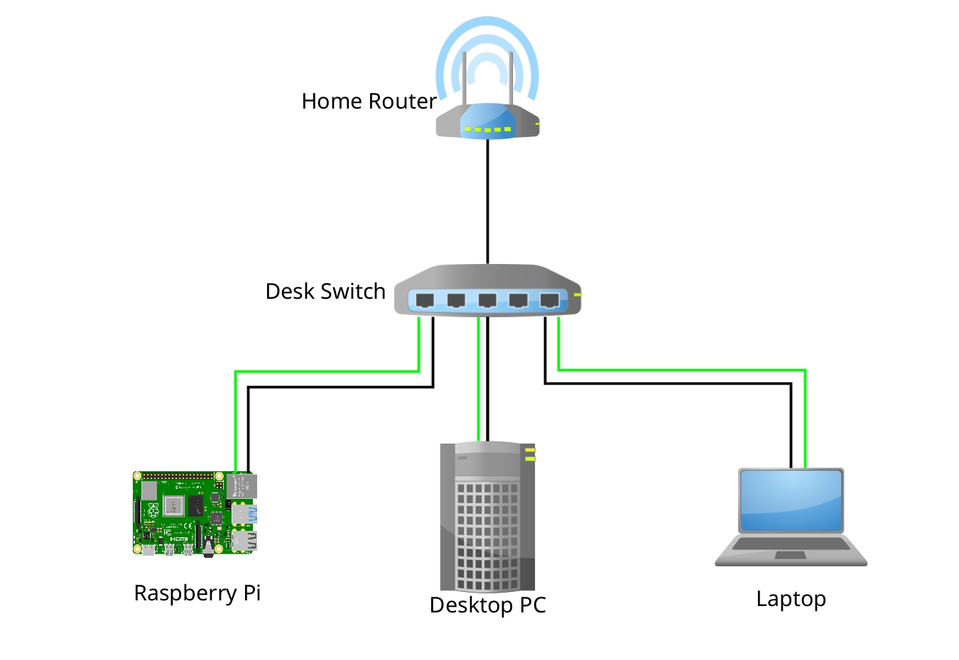
For over 10 years now, I run two self-built NAS (Network Storage) devices which serve media (currently via Jellyfin) and run daily backups of all my PCs and servers.
In this article, I describe my goals, which hardware I picked for my new build (and why) and how I set it up.
Design Goals
I use my network storage devices primarily for archival (daily backups), and secondarily as a media server.
There are days when I don’t consume any media (TV series and movies) from my NAS, because I have my music collection mirrored to another server that’s running 24/7 anyway. In total, my NAS runs for a few hours in some evenings, and for about an hour (daily backups) in the mornings.
This usage pattern is distinctly different than, for example, running a NAS as a file server for collaborative video editing that needs to be available 24/7.
When hardware breaks, I can get replacements from the local PC store the same day.
Even when only the data disk(s) survive, I should be able to access my data when booting a standard live Linux system.
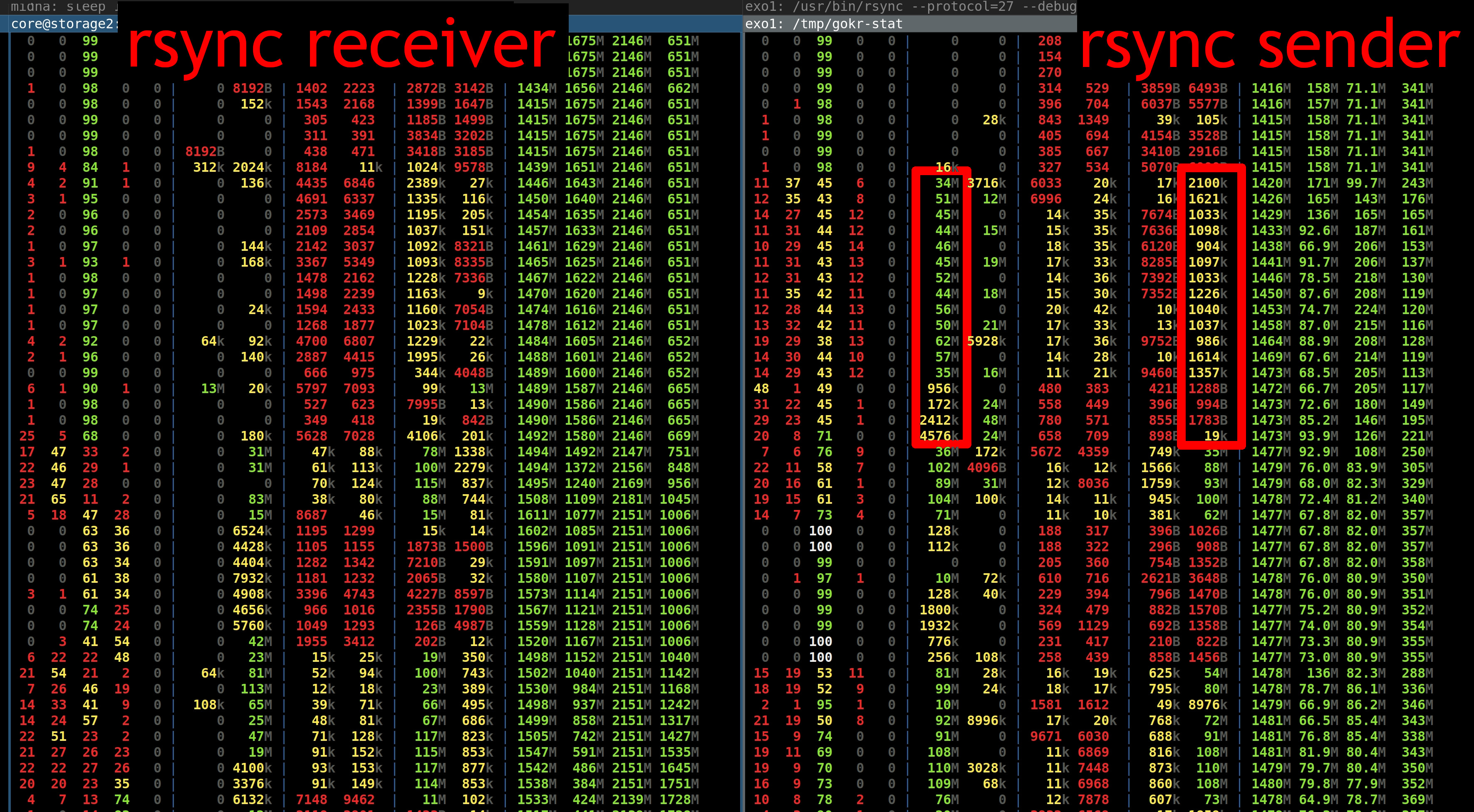
Minimal application software risk: I want to minimize risk for manual screw-ups or software bugs, meaning I use the venerable rsync for my backup needs (not Borg, restic, or similar).
Minimal system software risk: I use reliable file systems with the minimal feature set — no LVM or btrfs snapshots, no ZFS replication, etc. To achieve redundancy, I don’t use a cluster file system with replication, instead I synchronize my two NAS builds using rsync, without the --delete flag.
Minimal failure domains: when one NAS fails, the other one keeps working.
Having N+1 redundancy here takes the stress out of repairing your NAS.
I run each NAS in a separate room, so that accidents like fires or spilled drinks only affect one machine.
File System: ZFS
In this specific build, I am trying out ZFS. Because I have two NAS builds
running, it is easy to change one variable of the system (which file system to
use) in one build, without affecting the other build.
My main motivation for using ZFS instead of ext4 is that ZFS does data checksumming, whereas ext4 only checksums metadata and the journal, but not data at rest. With large enough datasets, the chance of bit flips increases significantly, and I would prefer to know about them so that I can restore the affected files from another copy.
Hardware
Each of the two storage builds has (almost) the same components. This makes it easy to diagnose one with the help of the other. When needed, I can swap out components of the second build to temporarily repair the first one, or vice versa.
The total price of 476 CHF makes this not a cheap build.
But, I think each component is well worth its price. Here’s my thinking regarding the components:
Why not a cheaper system disk? I wanted to use an M.2 NVMe disk so that I could mount it on the bottom of the mainboard instead of having to mount another SATA disk in the already-crowded case. Instead of chosing the cheapest M.2 disk I could find, I went with WD Red as a brand I recognize. While it’s not a lot of effort to re-install the system disk, it’s still annoying and something I want to avoid if possible. If spending 20 bucks saves me one disk swap + re-install, that’s well worth it for me!
Why not skip the system disk entirely and install on the data disks? That makes the system harder to (re-)install, and easier to make manual errors when recovering the system. I like to physically disconnect the data disks while re-installing a NAS, for example. (I’m a fan of simple precautions that prevent drastic mistakes!)
Why not a cheaper CPU cooler? In one of my earlier NAS builds, I used a (cheaper) passive CPU fan, which was directly in the air stream of the Noctua 120mm case fan. This setup was spec’ed for the CPU I used, and yet said CPU died as the only CPU to die on me in many many years. I want a reliable CPU fan, but also an absolutely silent build, so I went with the Noctua CPU cooler.
Why not skip the case fan, or go with the Silverstone-supplied one? You might argue that the airflow of the CPU cooler is sufficient for this entire build. Maybe that’s true, but I don’t want to risk it. Also, there are 3 disks (two data disks and one system disk) that can benefit from additional airflow.
Regarding the CPU, I chose the cheapest AMD CPU for Socket AM4, with a 35W TDP and built-in graphics. The built-in graphics means I can connect an HDMI monitor for setup and troubleshooting, without having to use the mainboard’s valuable one and only PCIe slot.
Unfortunately, AMD CPUs with 35W TDP are not readily available right now. My tip is to look around for a bit, and maybe buy a used one. Chose either the predecessor Athlon 200GE, or the newer generation Ryzen APU series, whichever you can get your hands on.
As a disclaimer: the two builds I use are very similar to the component list above, with the following differences:
On storage2, I use an old AMD Ryzen 5 5600X CPU instead of the listed Athlon 3000G. The extra performance isn’t needed, and the lack of integrated graphics is annoying. But, I had the CPU lying around and didn’t want it to go to waste.
On storage3, I use an old AMD Athlon 200GE CPU on an AsRock AB350 mainboard.
I didn’t describe the exact builds I use because a component list is more useful if the components on it are actually available :-).
16 TB SSD Data Disks
It used to be that Solid State Drives (SSDs) were just way too expensive compared to spinning hard disks when talking about terabyte sizes, so I used to put the largest single disk drive I could find into each NAS build: I started with 8 TB disks, then upgraded to 16 TB disks later.
Luckily, the price of flash storage has come down quite a bit: the Samsung SSD 870 QVO (8 TB) costs “only” 42 CHF per TB. For a total of 658 CHF, I can get 16 TB of flash storage in 2 drives:
Of course, spinning hard disks are at 16 CHF per TB, so going all-flash is over 3x as expensive.
I decided to pay the premium to get a number of benefits:
My NAS devices are quieter because there are no more spinning disks in them. This gives me more flexibility in where to physically locate each storage machine.
My daily backups run quicker, meaning each NAS needs to be powered on for less time. The effect was actually quite pronounced, because figuring out which files need backing up requires a lot of random disk access. My backups used to take about 1 hour, and now finish in less than 20 minutes.
The quick access times of SSDs solve the last remaining wrinkle in my backup scheme: deleting backups and measuring used disk space is finally fast!
Power Usage
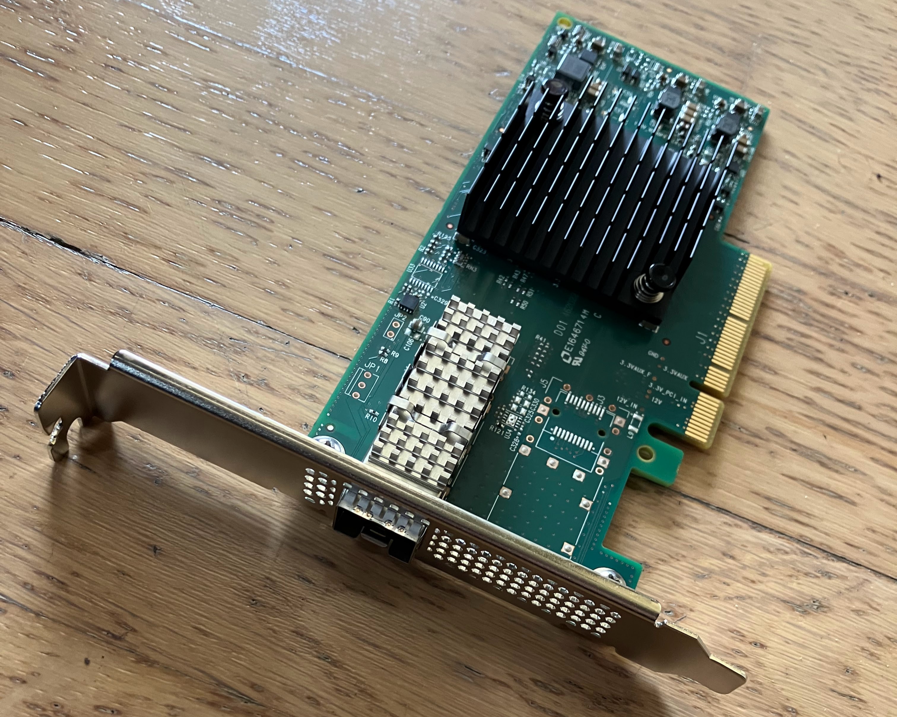
The choice of CPU, Mainboard and Network Card all influence the total power usage of the system. Here are a couple of measurements to give you a rough idea of the power usage:
Before this build, I ran my NAS using Docker containers on CoreOS (later renamed to Container Linux), which was a light-weight Linux distribution focused on containers. There are two parts about CoreOS that I liked most.
The most important part was that CoreOS updated automatically, using an A/B updating scheme, just like I do in gokrazy. I want to run as many of my devices as possible with A/B updates.
The other bit I like is that the configuration is very clearly separated from the OS. I managed the configuration (a cloud-init YAML file) on my main PC, so when swapping out the NAS system disk with a blank disk, I could just plug my config file into the CoreOS installer, and be done.
When CoreOS was bought by Red Hat and merged into Project Atomic, there wasn’t a good migration path and cloud-init wasn’t supported anymore. As a short-term solution, I switched from CoreOS to Flatcar Linux, a spiritual successor.
Now: Ubuntu Server
For this build, I wanted to try out ZFS. I always got the impression that ZFS was a pain to run because its kernel modules are not included in the upstream Linux kernel source.
Then, in 2016, Ubuntu decided to include ZFS by default. There are a couple of other Linux distributions on which ZFS seems easy enough to run, like Gentoo, Arch Linux or NixOS.
I wanted to spend my “innovation tokens” on ZFS, and keep the rest boring and similar to what I already know and work with, so I chose Ubuntu Server over NixOS. It’s similar enough to Debian that I don’t need to re-learn.
Luckily, the migration path from Flatcar’s cloud-init config to Ubuntu Server is really easy: just copy over parts of the cloud-config until you’re through the entire thing. It’s like a checklist!
Maybe later? gokrazy
In the future, it might be interesting to build a NAS setup using gokrazy. In particular since we now can run Docker containers on gokrazy, which makes running Samba or Jellyfin quite easy!
Using gokrazy instead of Ubuntu Server would get rid of a lot of moving parts. The current blocker is that ZFS is not available on gokrazy. Unfortunately that’s not easy to change, in particular also from a licensing perspective.
Setup
UEFI
I changed the following UEFI settings:
Advanced → ACPI Configuration → PCIE Devices Power On: Enabled
This setting is needed (but not sufficient) for Wake On LAN (WOL). You also need to enable WOL in your operating system.
Advanced → Onboard Devices Configuration → Restore on AC/Power Loss: Power On
This setting ensures the machine turns back on after a power loss. Without it, WOL might not work after a power loss.
Operating System
Network preparation
I like to configure static IP addresses for devices that are a permanent part of my network.
I have come to prefer configuring static addresses as static DHCP leases in my router, because then the address remains the same no matter which operating system I boot — whether it’s the installed one, or a live USB stick for debugging.
I initially let the setup program install Docker, but that’s a mistake. The setup program will get you Docker from snap (not apt), which can’t work with the whole file system.
Disable swap:
swapoff -a
$EDITOR /etc/fstab # delete the swap line
Automatically load the corresponding sensors kernel module for the mainboard so that the Prometheus node exporter picks up temperature values and fan speed values:
I have come to like Tailscale. It’s a mesh VPN (data flows directly between the machines) that allows me access to and from my PCs, servers and storage machines from anywhere.
For monitoring, I have an existing Prometheus setup. To add a new machine to my setup, I need to configure it as a new target on my Prometheus server. In addition, I need to set up Prometheus on the new machine.
First, I installed the Prometheus node exporter using apt install prometheus-node-exporter.
Then, I modified /etc/default/prometheus-node-exporter to only listen on the Tailscale IP address:
ARGS="--web.listen-address=100.85.3.16:9100"
Lastly, I added a systemd override to ensure the node exporter keeps trying to start until tailscale is up: the command systemctl edit prometheus-node-exporter opens an editor, and I configured the override like so:
# /etc/systemd/system/prometheus-node-exporter.service.d/override.conf
[Unit]
# Allow infinite restarts, even within a short time.
StartLimitIntervalSec=0

[Service]
RestartSec=1
Static IPv6 address
Similar to the static IPv4 address, I like to give my NAS a static IPv6 address as well. This way, I don’t need to reconfigure remote systems when I (sometimes temporarily) switch my NAS to a different network card with a different MAC address. Of course, this point becomes moot if I ever switch all my backups to Tailscale.
Ubuntu Server comes with Netplan by default, but I don’t know Netplan and don’t want to use it.
To switch to systemd-networkd, I ran:
apt remove --purge netplan.io
Then, I created a systemd-networkd config file with a static IPv6 token, resulting in a predictable IPv6 address:
An easy way to configure Linux’s netfilter firewall is to apt install iptables-persistent. That package takes care of saving firewall rules on shutdown and restoring them on the next system boot.
My rule setup is very simple: allow ICMP (IPv6 needs it), then set up ACCEPT rules for the traffic I expect, and DROP the rest.
Here’s my resulting /etc/iptables/rules.v6 from such a setup:
/etc/iptables/rules.v6
# Generated by ip6tables-save v1.4.14 on Fri Aug 26 19:57:51 2016
*filter
:INPUT DROP [0:0]
:FORWARD ACCEPT [0:0]
:OUTPUT ACCEPT [0:0]
-A INPUT -p ipv6-icmp -m comment --comment "IPv6 needs ICMPv6 to work" -j ACCEPT
-A INPUT -m state --state RELATED,ESTABLISHED -m comment --comment "Allow packets for outgoing connections" -j ACCEPT
-A INPUT -s fe80::/10 -d fe80::/10 -m comment --comment "Allow link-local traffic" -j ACCEPT
-A INPUT -s 2001:db8::/64 -m comment --comment "local traffic" -j ACCEPT
-A INPUT -p tcp -m tcp --dport 22 -m comment --comment "SSH" -j ACCEPT
COMMIT
# Completed on Fri Aug 26 19:57:51 2016
Encrypted ZFS
Before you can use ZFS, you need to install the ZFS tools using apt install zfsutils-linux.
The key I’m piping into zfs create is constructed from two halves: the on-device secret and the remote secret, which is a setup I’m using to implement an automated crypto unlock that is remotely revokable. See the next section for the corresponding unlock.service.
I repeated this same command (adjusting the dataset name) for each dataset: I currently have one for data and one for backup, just so that the used disk space of each major use case is separately visible:
On this machine, a scrub takes a little over 4 hours and keeps the disks busy:
  scan: scrub in progress since Wed Oct 11 16:32:05 2023
	808G scanned at 909M/s, 735G issued at 827M/s, 10.2T total
	0B repaired, 7.01% done, 03:21:02 to go
We can confirm by looking at the Prometheus Node Exporter metrics:
The other maintenance-related setting I changed is to enable automated TRIM:
zpool setautotrim=on srv
Auto Crypto Unlock
To automatically unlock the encrypted datasets at boot, I’m using a custom unlock.service systemd service file.
My unlock.service constructs the crypto key from two halves: the on-device secret and the remote secret that’s downloaded over HTTPS.
This way, my NAS can boot up automatically, but in an emergency I can remotely stop this mechanism.
My unlock.service
[Unit]Description=unlock hard driveWants=network.targetAfter=systemd-networkd-wait-online.serviceBefore=samba.service[Service]Type=oneshotRemainAfterExit=yes# Wait until the host is actually reachable.ExecStart=/bin/sh -c "c=0; while [ $c -lt 5 ]; do /bin/ping6 -n -c 1 autounlock.zekjur.net && break; c=$((c+1)); sleep 1; done"ExecStart=/bin/sh -c "(echo -n secret && wget --retry-connrefused -qO - https://autounlock.zekjur.net:8443/nascrypto) | zfs load-key srv/data"ExecStart=/bin/sh -c "(echo -n secret && wget --retry-connrefused -qO - https://autounlock.zekjur.net:8443/nascrypto) | zfs load-key srv/backup"ExecStart=/bin/sh -c "zfs mount srv/data"ExecStart=/bin/sh -c "zfs mount srv/backup"[Install]WantedBy=multi-user.target
Backup
For the last 10 years, I have been doing my backups using rsync.
Each machine pushes an incremental backup of its entire root file system (and any mounted file systems that should be backed up, too) to the backup destination (storage2/3).
All the machines I’m backing up run Linux and the ext4 file system. I verified that my backup destination file systems support all the features of the backup source file system that I care about, i.e. extended attributes and POSIX ACLs.
The scheduling of backups is done by “dornröschen”, a Go program that wakes up the backup sources and destination machines and starts the backup by triggering a command via SSH.
SSH configuration
The backup scheduler establishes an SSH connection to the backup source.
On the backup source, I authorized the scheduler like so, meaning it will run /root/backup.pl when connecting:
backup.pl runs rsync, which establishes another SSH connection, this time from the backup source to the backup destination.
On the backup destination (storage2/3), I authorize the backup source’s SSH public key to run rrsync(1)
, a script that only permits running rsync in the specified directory:
I found it easiest to signal readiness by starting an empty HTTP server gated on After=unlock.service in systemd:
/etc/systemd/system/healthz.service
[Unit]Description=nginx for /srv health checkWants=network.targetAfter=unlock.serviceRequires=unlock.serviceStartLimitInterval=0[Service]Restart=always# https://itectec.com/unixlinux/restarting-systemd-service-on-dependency-failure/ExecStartPre=/bin/sh -c 'systemctl is-active docker.service'# Stay on the same major version in the hope that nginx never decides to break# the config file syntax (or features) without doing a major version bump.ExecStartPre=/usr/bin/docker pull nginx:1ExecStartPre=-/usr/bin/docker kill nginx-healthzExecStartPre=-/usr/bin/docker rm -f nginx-healthzExecStart=/usr/bin/docker run \
--name nginx-healthz \
--publish 10.0.0.253:8200:80 \
--log-driver=journald \
nginx:1[Install]WantedBy=multi-user.target
My wake program then polls that port and returns once the server is up, i.e. the file system has been unlocked and mounted.
Auto Shutdown
Instead of explicitly triggering a shutdown from the scheduler program, I run “dramaqueen”, which shuts down the machine after 10 minutes, but will be inhibited while a backup is running. Optionally, shutting down can be inhibited while there are active samba sessions.
Luckily, the network driver of the onboard network card supports WOL by
default. If that’s not the case for your network card, see the Arch wiki
Wake-on-LAN article.
Conclusion
I have been running a PC-based few-large-disk Network Storage setup for years at this point, and I am very happy with all the properties of the system. I expect to run a very similar setup for years to come.
The low-tech approach to backups of using rsync has worked well — without changes — for years, and I don’t see rsync going away anytime soon.
The upgrade to all-flash is really nice in terms of random access time (for incremental backups) and to eliminate one of the largest sources of noise from my builds.
ZFS seems to work fine so far and is well-integrated into Ubuntu Server.
Related Options
There are solutions for almost everyone’s NAS needs. This build obviously hits my personal sweet spot, but your needs and preferences might be different!
Here are a couple of related solutions:
If you would like a more integrated solution, you could take a look at the Odroid H3 (Celeron).
If you’re okay with less compute power, but want more power efficiency, you could use an ARM64-based Single Board Computer.
If you want to buy a commercial solution, buy a device from qnap and fill it with SSD disks.
There are even commercial M.2 flash storage devices like the ASUSTOR Flashstor becoming available! If not for the “off the shelf hardware” goal of my build, this would probably be the most interesting commercial alternative to me.
If you want more compute power, consider a Thin Client (perhaps used) instead of a Single Board Computer.
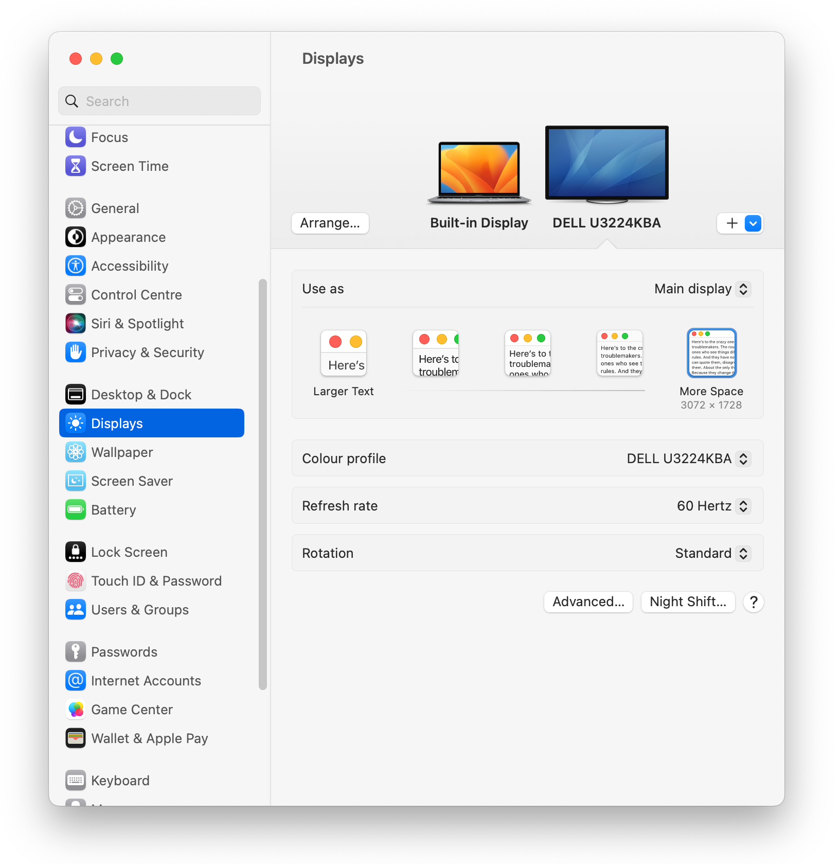
For the last 10 years, I have been interested in hi-DPI monitors, and recently I
read about an interesting new monitor: Dell’s 32-inch 6K monitor
(U3224KBA),
a productivity monitor that offers plenty of modern connectivity options like
DisplayPort 2, HDMI 2 and Thunderbolt 4.
My current monitor is a Dell 32-inch 8K monitor
(UP3218K), which has a brilliant picture, but
a few annoying connectivity limitations and quirks — it needs two (!)
DisplayPort cables on a GPU with MST support, meaning that in practice, it only
works with nVidia graphics cards.
I was curious to try out the new 6K monitor to see if it would improve the
following points:
Does the 6K monitor work well with most (all?) of my PCs and laptops?
Is 6K resolution enough, or would I miss the 8K resolution?
Is a matte screen the better option compared to the 8K monitor’s glossy finish?
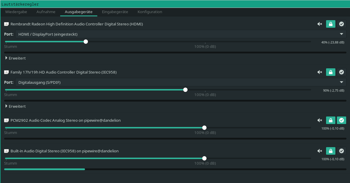
Do the built-in peripherals work with Linux out of the box?
I read a review on
heise+
(also included in their c’t magazine), but the review can’t answer these
subjective questions of mine.
So I ordered one and tried it out!
Compatibility
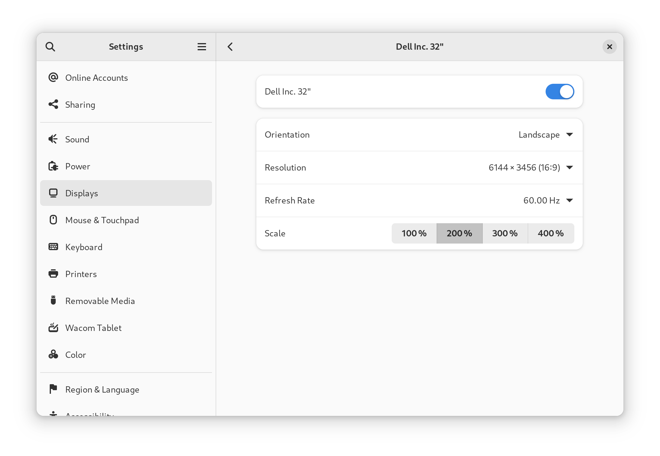
The native resolution of this monitor is 6144x3456 pixels.
To drive that resolution at 60 Hz, about 34 Gbps of data rate is needed.
DisplayPort 1.4a only offers a data rate of 25 Gbps, so your hardware and driver
need to support Display Stream Compression
(DSC) to reach the
full resolution at 60 Hz. I tried using DisplayPort 2.0, which supports 77 Gbps
of data rate, but the only GPU I have that supports DisplayPort 2 is the Intel
A380, which I could not get to work well with this monitor (see the next
section).
HDMI 2.1 offers 42 Gbps of data rate, but in my setup, the link would still
always use DSC.
Here are the combinations I have successfully tried:
Device
Cable
OS / Driver
Resolution
MacBook Air M1
TB 3
macOS 13.4.1
native @ 60 Hz, 8.1Gbps
GeForce RTX 4070 (DisplayPort 1.4a)
mDP-DP
Windows 11 21H2
native @ 60 Hz, 12Gbps DSC
GeForce RTX 4070
mDP-DP
Linux 6.3 nVidia 535.54.03
native @ 60 Hz, 8.1Gbps DSC
GeForce RTX 4070 (HDMI 2.1a)
HDMI
Windows 11 21H2
native @ 60 Hz, 8.1Gbps DSC
GeForce RTX 4070
HDMI
Linux 6.3 nVidia 535.54.03
native @ 60 Hz, 6Gbps 3CH DSC
GeForce RTX 3060
HDMI
Linux 6.3 nVidia 535.54.03
native @ 60 Hz, 6Gbps 3CH DSC
ThinkPad X1 Extreme
TB 4
Linux 6.3 nVidia 535.54.03
native @ 60 Hz, 8.1Gbps DSC
The MacBook Air is the only device in my test that reaches full resolution
without using DSC.
Compatibility issues
Let’s talk about the combinations that did not work well.
Too old nVidia driver (< 535.54.03): not at native resolution
You need a quite recent version of the nVidia driver, as they just recentlyshipped support for
DSC at high
resolutions. I successfully used DSC with 535.54.03.
With the “older” 530.41.03, I could only select 6016x3384 at 60 Hz, which is not
the native resolution of 6144x3456 at 60 Hz.
Device
Cable
OS / Driver
Resolution
GeForce RTX 4070 (DisplayPort 1.4a)
mDP-DP
Linux 6.3 nVidia 530.41.03
native @ 30 Hz only, 6016x3384@60
GeForce RTX 4070 (HDMI 2.1a)
HDMI
Linux 6.3 nVidia 530.41.03
native @ 30 Hz only, 6016x3384@60
Intel GPU: no picture or only 4K?!
I was so excited when Intel announced that they are entering the graphics card
business. With all the experience and driver support for their integrated
graphics, I hoped for good Linux support.
Unfortunately, the Intel A380 I bought months ago continues to disappoint.
I could not get the 6K monitor to work at any resolution higher than 4K, not
even under Windows. Worse, when connecting the monitor using DisplayPort, I
wouldn’t get a picture at all (in Linux)!
Device
Cable
OS / Driver
Resolution
ASRock Intel A380 (DisplayPort 2.0)
mDP-DP
Windows 11 21H2 Intel 31.0.101.4502
only 4K @ 60 Hz
ASRock Intel A380 (HDMI 2.0b)
HDMI
Windows 11 21H2 Intel 31.0.101.4502
only 4K @ 60 Hz
ASRock Intel A380 (DisplayPort 2.0)
mDP-DP
Linux 6.4
no picture in Xorg!
ASRock Intel A380 (HDMI 2.0b)
HDMI
Linux 6.4
only 4K @ 60 Hz
No picture after resume from suspend-to-RAM
I suspend my PC to RAM at least once per day, sometimes even more often.
With my current 8K monitor, I have nailed the suspend/wakeup procedure. With the
help of a smart plug, I’m automatically turning the monitor off (on suspend) and
on (on wakeup). After a couple of seconds of delay, I configure the correct
resolution using xrandr.
I had hoped that the 6K monitor would make any sort of intricate automation
superfluous.
Unfortunately, when I resumed my PC, I noticed that the monitor would not show a
picture at all! I had to log in from my laptop via SSH to change the resolution
with xrandr to 4K, then power the monitor off and on again, then change
resolution back to the native 6K.
Scaling
Once you have a physical connection established, how do you configure your
computer? With 6K at 32 inches, you’ll need to enable some kind of scaling in
order to comfortably read text.
This section shows what options Linux and macOS offer.
i3 (X11)
Just like many other programs on Linux, you configure i3’s scaling by setting
the Xft.dpi X
resource. The default is 96
dpi, so to get 200% scaling, set Xft.dpi: 192.
Personally, I found 240% scaling more comfortable, i.e. Xft.dpi: 230.
This corresponds to a logical resolution of 2560x1440 pixels.
GNOME (Wayland)
I figured I’d also give Wayland a shot, so I ran GNOME in Fedora 38 on my
ThinkPad X1 Extreme.
Here’s what the settings app shows in its “Displays” tab:
When connecting the monitor to my MacBook Air M1 (2020), it defaults to a
logical resolution of 3072x1728, i.e. 200% scaling.
For comparison, with Apple’s (5K) Studio
Display, the default setting is
2560x1440 (200% scaling), or 2880x1620 (“More Space”, 177% scaling).
Observations
Matte screen
I remember the uproar when Lenovo introduced ThinkPads with glossy screens. At
the time, I thought I prefer matte screens, but over the years, I heard that
glossy screens are getting better and better, and consumers typically prefer
them for their better picture quality.
The 8K monitor I’m using has a glossy screen on which reflections are quite
visible. The MacBook Air’s screen shows fewer reflections in comparison.
Dell’s 6K monitor offers me a nice opportunity to see which option I prefer.
Surprisingly, I found that I don’t like the matte screen better!
It’s hard to describe, but somehow the picture seems more “dull”, or less bright
(independent of the actual brightness of the monitor), or more toned down. The
colors don’t pop as much.
Philosophical question: peripherals powered on by default?
One thing that I did not anticipate beforehand is the difference in how
peripherals are treated when they are built into the monitor vs. when they are
plugged into a USB hub.
I like to have my peripherals off-by-default, with “on” being the exceptional
state. In fact, I leave my microphone disconnected and only plug its USB cable
in when I need it. I also recently realized that I want sound to only be played
on headphones, so I disconnected my normal speakers in favor of my Bluetooth
dongle.
The 6K monitor, on the other hand, has all of its peripherals on-by-default, and
bright red LEDs light up when the speaker or microphone is muted.
This is the opposite of how I want my peripherals to behave, but of course I
understand why Dell developed the monitor with on-by-default peripherals.
Conclusion
Let’s go back to the questions I started the article with and answer them one by one:
Does the 6K monitor work well with most (all?) of my PCs and laptops?
→ Answer: The 6K monitor works a lot better than the 8K monitor, but that’s a
low bar to clear. I would still call the 6K monitor finicky. Even when you
run a latest-gen GPU with latest drivers, the monitor does not reliably show
a picture after a suspend/resume cycle.
Is 6K resolution enough, or would I miss the 8K resolution?
→ Answer: I had really hoped that 6K would turn out to be enough, but the
difference to 8K is visible with the bare eye. Just like 200% scaling is a
nice step up from working at 96 dpi, 300% scaling (what I use on 8K) is
another noticeable step up.
Is a matte screen the better option compared to the 8K monitor’s glossy finish?
→ Answer: While I don’t like the reflections in Dell’s 8K monitor, the
picture quality is undeniably better compared to a matte screen. The 6K
monitor just doesn’t look as good, and it’s not just about the difference in
text sharpness.
Do the built-in peripherals work with Linux out of the box?
→ Answer: Yes, as far as I can tell. The webcam works fine with the
generic uvcvideo USB webcam driver, the microphone and speakers work out of
the box. I have not tested the presence sensor.
So, would I recommend the monitor? Depends on what you’re using as your current
monitor and as the device you want to connect!
If you’re coming from a 4K display, the 6K resolution will be a nice step
up. Connecting a MacBook Air M1 or newer is a great experience. If you want to
connect PCs, be sure to use a new-enough nVidia GPU with latest drivers. Even
under these ideal conditions, you might run into quirks like the no picture
after resume problem. If you don’t mind early adopter pains like that,
and are looking for a monitor that includes peripherals, go for it!
For me, switching from my 8K monitor would be a downgrade without enough
benefits.
The ideal monitor for me would be a mixture between Dell’s 8K and 6K models:
8K resolution
…but with more modern connectivity options (one cable! works out of the box!).
without built-in peripherals like webcam, microphone and speaker
…but with the USB KVM switch concept (monitor input coupled to USB upstream).
glossy finish for best picture quality
…but with fewer reflections.
Maybe they’ll develop an updated version of the 8K monitor at some point?
With the team surrounding our previous paper on
reduced-basis methods for quantum spin systems,
Matteo Rizzi, Benjamin Stamm and Stefan Wessel and myself,
we recently worked on a follow-up, extending our approach to tensor-network methods.
Most of the work was done by Paul Brehmer,
a master student in Stefan's group, whom I had the pleasure to co-supervise.
Paul did an excellent job in cleaning up and extending the original code we had,
which we have now released in open-source form as the ReducedBasis.jl
Julia package.
The extension towards tensor-network methods and the integration
with libraries such as ITensor.jl
following the standard density-matrix renormalisation group (DMRG) approach,
finally allows us to treat larger quantum spin systems,
closer or at the level of the state of the art.
In this work we demonstrate this by a number of different one-dimensional
quantum spin-1 models, where our approach allowed us even to
identify a few new phases, which have not been studied so far.
The full abstract of our paper reads
Within the reduced basis methods approach, an effective low-dimensional
subspace of a quantum many-body Hilbert space is constructed in order to
investigate, e.g., the ground-state phase diagram. The basis of this
subspace is built from solutions of snapshots, i.e., ground states
corresponding to particular and well-chosen parameter values. Here, we show
how a greedy strategy to assemble the reduced basis and thus to select the
parameter points can be implemented based on matrix-product-states (MPS)
calculations. Once the reduced basis has been obtained, observables required
for the computation of phase diagrams can be computed with a computational
complexity independent of the underlying Hilbert space for any parameter
value. We illustrate the efficiency and accuracy of this approach for
different one-dimensional quantum spin-1 models, including anisotropic as
well as biquadratic exchange interactions, leading to rich quantum phase
diagrams.
In the past month I have renovated my appartment. Because of this I had to redo my entire desk setup. If you know me that means spending a lot time managing cables 😅.
But I am really happy with the result. See for yourself …
I always wanted to be flexible in how I use the devices on my desk. I want to switch between using my laptop and desktop without having to replug everything.
But I also want to be able to use certain devices from both at the same time. I have been using USB Hubs and the like. But I always was left wanting.
To be fair my current solution is still not as perfect as in my dreams, but it is damn close.
So lets begin with the easy things. The monitors have multiple inputs, so I just connect those to my desktop and the docking station and voila. Well switching still requires me
to use the monitor menus, but that I don’t really need to do that because I set them to “automatic mode” meaning the just show which ever device starts sending data first. And I don’t really
need to use all monitors with the laptop when my desktop is running anyway so switching does not happen much.
For the keyboard and mouse I am using the “Logitech MX” keyboard and “Logitech MX Master” mouse. The can be paired with multiple Logitech wireless receivers. The devices can the be switch with
the press of a button. Sadly switching one does not switch the other automatically which is still a little annyoing but I have seen some scripts that could be used to automate that as well.
Maybe I will give that a shot. I still have a “USB Switch” which is connected to the desktop and laptop, it has a switch to toggle which device is “connected”. I mostly use it for my yubikey
now. It also was fine for switching my previous mouse and keyboard.
There is still some room for improvements here, but that is not what has been bugging me. The parts I really wanted to be better are the Speakers, Microphone and the Webcam. In an ideal world
they should be accessible on either device or both at the same time. Hence the USB Switch is not a good solution since that only enables operation with a single device at a time. Also using the
USB switch is annyoing for other reasons. It means the audio dac is reset when switching devices resulting in an unpleasent noise coming out of my speakers. And also having all devices
connected to a switch takes away the ability to attach usb sticks or other devices that i really only need temporarily and daisy chaning usb hubs often results in inconsistent behavior.
What would be a better solution?
Enter everybodies favorite single board computer the Raspberry Pi 🥧. Luckly I still have one lying around since getting one online is next to impossible if you don’t want to pay a scalper
an unreasonable amount of money. Hopefully this will change. But anyway how can it help me acomplish my goal.
Thanks to a little something called networking computers can talk to each other. So it should be possible to attach the audio dac and webcam to the pi and then stream the video and audio data
to both the laptop and desktop. What do we need to accomplish that.
Configure the Network
Setup Pipewire to run as system service
Enable audio streaming with the pipewire pulse server implementation
Enable laptop and desktop to discover audio devices
Setup USBIP for sharing the webcam
Network Setup
I do not want to share the devices with my entire home network, I just want to share with devices attached to the desk. Since the raspberry only has one network jack and using wireless for
streaming data is not a great idea because of increased latency, the first thing I did was setup VLAN that is only availible to the devices on my desk.
First of the network switch needs to support VLANs, there are a lot of switches capable of doing this. They are a little more expensive then unmanged switches, but a basic models are
availible starting at around 30€. I opted for a more expensive model from microtik (CSS610-8G-2S+) that is also able to support fibre glas connections instead of just RJ45. Then
I configured the switch to setup the home network on each port in untagged mode. Then I created a VLAN with ID 2668 which will only be availible on the ports attached to the raspberry pi,
desktop and laptop in tagged mode. The choise of the ID is arbirary, just make sure to not have clashes with other VLAN if you already have a more elaborate network setup at home.
Next the devices need to be configured to know about the VLAN and the IP address range needs to be configured. I like to use systemd-networkd for this. The configuration
is done with three files in the /etc/systemd/network directory.
[root@pi ~]# tree /etc/systemd/network/etc/systemd/network
|-- 0-audio.netdev
|-- 1-audio.network
`-- eth.network
The file 0-audio.netdev defines the VLAN:
[NetDev]Name=audioKind=vlan[VLAN]Id=2668
The file eth.network configures the normal home network on the pi, here we need to add a line specifing that the VLAN is availible on this port:
Lastly the VLAN network needs to be configured. Since the pi is running continously it is useful to configure its ip statically and setup a DHCP server.
All of this is configured with just a few lines in the 1-audio.network file.
The same steps are used to configure the VLAN on the desktop and laptop, the only things that change are the interface names for the home network and that the audio vlans network can use the configured DHCP server to obtain a lease. Resulting in the follwing 1-audio.network file on the clients.
[Match]Name=audio[Network]DHCP=yes
Of course to use systemd-networkd the service needs to be enabled: systemctl enable --now systemd-networkd.
Pipewire System Service
Pipewire intends to be a modern linux media deamon. It is still in active development. For now it already can be used as a replacement for pulseaudio or jack.
Normally pipewire starts when you login to your user session. But since there is no desktop running on the pi pipewire needs to be configured to run as a system
service.
First of the software packages need to be installed. I am more of a minimalist when it comes to the systems I configure, means I am running archlinux on the raspberry
pi. The packages names might vary if you are running raspbian. For me doning
installed all desired packages. There is not a lot of documentation on how to setup pipewire as a system service. I found
this issue thread which lists all the steps required.
Maybe the process will get simpler in the future, but for now a lot of steps are required.
First a pipewire user and group needs to be created with a statically assigned uid and gid. This is important to correctly set the environment variables in the service
files created later. The pipewire user needs to be added to the audio and realtime group.
addgroup --gid 901 pipewire
adduser --system  --uid 091 --gid 901 pipewire
for g in audio realtime; do sudo adduser pipewire ${g}; done
Next we need to add a configuration file /etc/security/limits.d/99-realtime-privileges.conf to allow the realtime group to change the process priorities to the levels recommended
by pipewire.
With the limits in place, the next step is to setup systemd units for pipewire, pipewire-pulse and wireplumber. In total 5 files need to be created:
/etc/systemd/system/pipewire.socket
/etc/systemd/system/pipewire.service
/etc/systemd/system/pipewire-pulse.socket
/etc/systemd/system/pipewire-pulse.service
/etc/systemd/system/wireplumber.service
The content of these files is as follows.
#/etc/systemd/system/pipewire.socket[Unit]Description=PipeWire Multimedia System Socket[Socket]Priority=6ListenStream=%t/pipewire/pipewire-0SocketUser=pipewireSocketGroup=pipewireSocketMode=0660[Install]WantedBy=sockets.target
#/etc/systemd/system/pipewire.service[Unit]Description=PipeWire Multimedia ServiceBefore=gdm.service# We require pipewire.socket to be active before starting the daemon, because# while it is possible to use the service without the socket, it is not clear# why it would be desirable.## Installing pipewire and doing `systemctl start pipewire` will not get the# socket started, which might be confusing and problematic if the server is to# be restarted later on, as the client autospawn feature might kick in. Also, a# start of the socket unit will fail, adding to the confusion.## After=pipewire.socket is not needed, as it is already implicit in the# socket-service relationship, see systemd.socket(5).Requires=pipewire.socket[Service]User=pipewireType=simpleExecStart=/usr/bin/pipewireRestart=on-failureRuntimeDirectory=pipewireRuntimeDirectoryPreserve=yesEnvironment=PIPEWIRE_RUNTIME_DIR=%t/pipewire# Add if you need debugging# Environment=PIPEWIRE_DEBUG=4# These hardcoded runtime and dbus paths must stay this way for a system service# as the User= is not resolved here 8(## NOTE we do not change PIPEWIRE_RUNTIME_DIR as this is the system socket dir...#Environment=PIPEWIRE_RUNTIME_DIR=/run/user/91/pipewireEnvironment=XDG_RUNTIME_DIR=/run/user/91Environment=DBUS_SESSION_BUS_ADDRESS=unix:path=/run/user/91/bus
#/etc/systemd/system/pipewire-pulse.service[Unit]Description=PipeWire PulseAudio# We require pipewire-pulse.socket to be active before starting the daemon, because# while it is possible to use the service without the socket, it is not clear# why it would be desirable.## A user installing pipewire and doing `systemctl --user start pipewire-pulse`# will not get the socket started, which might be confusing and problematic if# the server is to be restarted later on, as the client autospawn feature# might kick in. Also, a start of the socket unit will fail, adding to the# confusion.## After=pipewire-pulse.socket is not needed, as it is already implicit in the# socket-service relationship, see systemd.socket(5).Requires=pipewire-pulse.socketWants=pipewire.service pipewire-session-manager.serviceAfter=pipewire.service pipewire-session-manager.serviceConflicts=pulseaudio.service# To ensure that multiple user instances are not created. May not be requieredBefore=gdm.service[Service]User=pipewireType=simpleExecStart=/usr/bin/pipewire-pulseRestart=on-failureSlice=session.slice# These hardcoded runtime and dbus paths must stay this way for a system service# as the User= is not resolved here 8(Environment=PULSE_RUNTIME_PATH=/home/pipewireEnvironment=DBUS_SESSION_BUS_ADDRESS=unix:path=/run/user/91/bus[Install]Also=pipewire-pulse.socketWantedBy=multi-user.target
#/etc/systemd/system/wireplumber.service [Unit]Description=Multimedia Service Session ManagerAfter=pipewire.serviceBindsTo=pipewire.serviceConflicts=pipewire-media-session.service[Service]User=pipewireType=simpleExecStart=/usr/bin/wireplumberRestart=on-failureSlice=session.slice# These hardcoded runtime and dbus paths must stay this way for a system service# as the User= is not resolved here 8(Environment=XDG_RUNTIME_DIR=/run/user/91Environment=DBUS_SESSION_BUS_ADDRESS=unix:path=/run/user/91/bus[Install]WantedBy=pipewire.serviceAlias=pipewire-session-manager.service
For the services to work correctly we need a running user session with dbus. This can be acomplished by telling loginctl to start a pipewire user session at system boot:
loginctl enable-linger pipewire
Since running pipewire on the pi as a user is undesired the user services need to be masked.
At this point piperwire is running on the raspberry after boot up. The next step is to setup network streaming. Thankfully that is easly done in two steps:
Setup Pipewire on the Raspberry Pi to be reachable via the VLAN and enable publishing of its devices via zeroconf
Setup clients (laptop, desktop) to listen for zeroconf announcements
For compatibility with the existing playback methods and to be a “drop-in” replacement pipewire has implementated a full pulseaudio server on top of itself.
This way existing tools for managing audio playback and recording can still be used like pavucontrol. Pulseaudio supported being used over a network. This is not low latency
so doing this over wifi is not really recommended, but over a wired connection the latencies are so low that it is not noticable. Pipewire supports this as well.
So all we need to do to create a configuration file to configure network access:
# /etc/pipewire/pipewire-pulse.conf.d/network.conf
pulse.properties = {
    # the addresses this server listens on
    pulse.min.frag = 32/48000           #0.5ms
    pulse.default.frag = 256/48000       #5ms
    pulse.min.quantum = 32/48000        #0.5ms
    server.address = [
        "unix:native"
        #"unix:/tmp/something"              # absolute paths may be used
        #"tcp:4713"                         # IPv4 and IPv6 on all addresses
        #"tcp:[::]:9999"                    # IPv6 on all addresses
        #"tcp:127.0.0.1:8888"               # IPv4 on a single address
        #
        { address = "tcp:172.16.128.1:4713"             # address
          max-clients = 64                 # maximum number of clients
          listen-backlog = 32              # backlog in the server listen queue
          client.access = "allowed"     # permissions for clients
        }
    ]
}
Per default piperwire-pulse only enables the “unix:native” socket for access via dbus. To enable the network streaming the last 4 lines starting with address are of interest.
In order to restict access to the VLAN the Ip address of the raspberry pi in the audio network needs to be specified. Also the client.access value needs to be set to “allowed” in order to enable
all devices on that network to use it.
I also had to decrease the default values for pulse.min.frag, pulse.default.frag and pulse.min.quantum quite a bit in order for the latency of the mircophone to be usable while in a video
call. Otherwise video and audio would be very out of sink. The pipewire documentation warns that this will increase CPU usage. I have not noticed a big impact on the raspberry pi 4 I am using to
do this.
Next enabling the publishing of the pipewire server via zeroconf needs to be enabled. This could be done in the same configuration file. But for better overview over the configuration a created
an extra configuration file:
Thats really short. All we are doing is to tell the pulseaudio server to enable the zeroconf publish module. And on the clients we need to enable zeroconf discovery like this:
For this to work the zeroconf deamon needs to be running. On linux the zeroconf implementation is provided by avahi. Most systems probably have it running already.
On archlinux enable the avaih-daemon via systemd. The daemon also needs to be running on the raspberry pi for the publishing to work.
If everything worked correctly you should see the audio devices attached to the pi pop up in pavucontrol (after restarting the pipewire-pulse service for the configuration to apply):
Selecting the playback device or mircophone phone should now just work like with a locally attached the device. The really nice thing about this is that you can even use the devices from
multiple clients at the same time!!!
Webcam
In theory pipewire is was written for camera device sharing between multiple applications. For example the webcam software cheese is already using pipewire. But I have found absolutly
zero infromation if it whould be possible to do that via a network. Im not even really sure that this is on the roadmap. If it is I will definitly revisit this topic. The only other option I could think of was to somehow use some form of continous webcam broadcast that I could then somehow attach as a camera, but I also do not want the webcam to be active all the time.
So the solution I have come up with for now is to use USBIP. Which is a client server application to speak the USB protocol via the network. This comes with the drawback that the webcam
can only be used by one device at a time, but at least I do not have to physically replug the device. Just issue a command to attach and detach it.
This can be done in a few simple steps:
Install usbip on server (pi) and client (laptop, desktop)
Enable the Service on both devices.
On pi bind webcam to usbip daemon
Attach/detach webcam via usbip daemon on the client
So the first to steps are the same for the client and server: Install the usbip package. Depending on your distribution it might be named differently.
The enable the service using systemd: systemctl enable --now usbipd.
The next step is to bind the webcam to the usbipd daemon on the raspberry pi. For this the busid of the device needs to be found. This can be done by
using the usbip utility:
With the webcam attached it can be used like any other webcam. For example you could open cheese and take a picture:
After usage the webcam should be detached again, to make it possible for other clients to connect to it. If you forget to detach before powering of the device currently using the camera. You
will login to the pi to unbind and rebind the device again, since usbip does not seem to have a timeout mechanism. A few other things to note about this setup are:
It is still not possible to use the device from multiple clients at the same time 😥
To make sure that the camera can only be used via the local VLAN a firewall configuration on the pi is required, since usbip is not confuriable to only listen on a certain network interface.
If you are getting an error when attaching the camera, you might also need to make sure the vhci-hcd kernel module is loaded!
I hope you enjoyed this post. If you have any further thoughts or questions. Feel free to reach out to me.
gokrazy is an appliance platform for Go programs: with
just a few commands, you can deploy your Go program(s) on a Raspberry Pi or a
(typically small) PC.
I’m excited to let you know that gokrazy now comes with a re-designed gok
command line tool and gokrazy instance configuration mechanism!
Context: gokrazy in a few words
The traditional way to run Go software on a Raspberry Pi would be to install
Raspbian or some other Linux distribution onto the SD card, copy over your
program(s) and then maintain that installation (do regular updates).
I thought it would be nicer to run my Raspberry Pis such that only Go
software is run by the Linux kernel on it, without any traditional Linux
distribution programs like package managers or even the usual GNU Core
Utilities.
gokrazy builds Go programs into a read-only SquashFS root file system
image. When that image is started on a Raspberry Pi, a minimal init system
supervises the Go programs, and a DHCP and NTP client configure the IP address
and synchronize the time, respectively. After the first installation, all
subsequent updates can be done over the network, with an A/B partitioning
scheme.
Previously, the concept of gokrazy instance configuration was only a
convention. Each gokrazy build was created using the gokr-packer CLI tool, and
configured by the packer’s command-line flags, parameters, config files in
~/.config and per-package config files in the current directory
(e.g. flags/github.com/gokrazy/breakglass/flags.txt).
Now, all gokrazy commands and tools understand the --instance flag (or -i
for short), which determines the directory from which the Instance
Config is read. For a gokrazy
instance named “hello”, the default directory is ~/gokrazy/hello, which
contains the config.json file.
Example: creating an instance for a Go working copy
Let’s say I have the evcc repository cloned
as ~/src/evcc. evcc is an electric vehicle charge controller with PV
integration, written in Go.
Now I want to run evcc on my Raspberry Pi using gokrazy. First, I create a new
instance:
% gok -i evcc new
gokrazy instance configuration created in /home/michael/gokrazy/evcc/config.json
(Use 'gok -i evcc edit' to edit the configuration interactively.)Use 'gok -i evcc add' to add packages to this instance
To deploy this gokrazy instance, see 'gok help overwrite'
Now let’s add our working copy of evcc to the instance:
% gok -i evcc add .
2023/01/15 18:55:39 Adding the following package to gokrazy instance "evcc":
Go package : github.com/evcc-io/evcc
in Go module: github.com/evcc-io/evcc
in local dir: /tmp/evcc
2023/01/15 18:55:39 Creating gokrazy builddir for package github.com/evcc-io/evcc
2023/01/15 18:55:39 Creating go.mod with replace directive
go: creating new go.mod: module gokrazy/build/github.com/evcc-io/evcc
2023/01/15 18:55:39 Adding package to gokrazy config
2023/01/15 18:55:39 All done! Next, use 'gok overwrite'(first deployment), 'gok update'(following deployments) or 'gok run'(run on running instance temporarily)
We might want to monitor this Raspberry Pi’s stats later, so let’s add the
Prometheus node exporter to our gokrazy instance, too:
% gok -i evcc add github.com/prometheus/node_exporter
2023/01/15 19:04:05 Adding github.com/prometheus/node_exporter as a (non-local) package to gokrazy instance evcc
2023/01/15 19:04:05 Creating gokrazy builddir for package github.com/prometheus/node_exporter
2023/01/15 19:04:05 Creating go.mod before calling go get
go: creating new go.mod: module gokrazy/build/github.com/prometheus/node_exporter
2023/01/15 19:04:05 running [go get github.com/prometheus/node_exporter@latest]go: downloading github.com/prometheus/node_exporter v1.5.0
[…]2023/01/15 19:04:07 Adding package to gokrazy config
It’s time to insert an SD card (/dev/sdx), which we will overwrite with a
gokrazy build:
The new gok subcommands (add, update, etc.) are much easier to manage than
long gokr-packer command lines.
The new Automation page shows how
to automate common tasks, be it daily updates via cron, or automated building
in Continuous Integration environments like GitHub Actions.
Migration
Are you already a gokrazy user? If so, see the Instance Config Migration
Guide for how to switch from
the old gokr-packer tool to the new gok command.
Similar to most people in their second PostDoc a considerable chunk of time in the past year
has been devoted to job hunting, i.e. writing applications, preparing and attending interviews
for junior research group positions. As the year is closing I am finally able to make a positive
announcement in this regard:
The Swiss ETH board has appointed me as
Tenure Track Assistant Professor of Mathematics and of Materials Science and Engineering at EPF Lausanne,
a position I am more than happy to take up.
From March 2023 I will thus join this school and as part of this interdisciplinary
appointment establish a research group located in both the mathematics and materials science institutes.
I am very grateful to the search committee as well as the ETH board and the university
for this opportunity to start my own group and to be able to continue my research agenda
combining ideas from mathematics and computer science to make materials simulations
more robust and efficient. I look forward to becoming a part of the EPFL research environment
and being able to contribute to the training of next generation researchers.
Along the lines of this appointment I now also have a few vacancies at PhD and PostDoc level to fill.
Further information will be posted here as well as standard channels of the community early next year.
Note: If you don’t want to read the exposition and explanations and just want
to know the steps I did, scroll to the summary at the bottom.
For a couple of years I have (with varying degrees of commitment) participated
in Advent of Code, a yearly programming
competition. It consists of fun little daily challenges. It is great to
exercise your coding muscles and can provide opportunity to learn new languages
and technologies.
So far I have created a separate repository for each year, with a directory
per day. But I decided that I’d prefer to have a single repository, containing
my solutions for all years. The main reason is that I tend to write little
helpers that I would like to re-use between years.
When merging the repositories it was important to me to preserve the history
of the individual years as well, though. I googled around for how to do this
and the solutions I found didn’t quite work for me. So I thought I should
document my own solution, in case anyone finds it useful.
You can see the result here.
As you can see, there are four cleanly disjoint branches with separate
histories. They then merge into one single commit.
One neat effect of this is that the merged repository functions as a normal
remote for all the four old repositories. It involves no rewrites of history
and all the previous commits are preserved exactly as-is. So you can just git pull from this new repository and git will fast-forward the branch.
Step 1: Prepare individual repositories
First I went through all repositories and prepared them. I wanted to have the
years in individual directories. In theory, it is possible to use
git-filter-repo and similar
tooling to automate this step. For larger projects this might be worth it.
I found it simpler to manually make the changes in the individual repositories
and commit them. In particular, I did not only need to move the files to the
sub directory, I also had to fix up Go module and import paths. Figuring out
how to automate that seemed like a chore. But doing it manually is a quick and
easy sed command.
You can see an example of that
in this commit.
While that link points at the final, merged repository, I created the commit in
the old repository. You can see that a lot of files simply moved. But some also
had additional changes.
You can also see that I left the go.mod in the top-level directory. That was
intentional - I want the final repository to share a single module, so that’s
where the go.mod belongs.
After this I was left with four repositories, each of which had all the
solutions in their own subdirectory, with a go.mod/go.sum file with the
shared module path. I tested that all solutions still compile and appeared to
work and moved on.
Step 2: Prepare merged repository
The next step is to create a new repository which can reference commits and
objects in all the other repos. After all, it needs to contain the individual
histories. This is simple by setting the individual repositories as remotes:
One thing worth pointing out is that at this point, the merged AdventOfCode
repository does not have any branches itself. The only existing branches are
remotes/ references. This is relevant because we don’t want our resulting
histories to share any common ancestor. And because git behaves slightly
differently in an empty repository. A lot of commands operate on HEAD (the
“current branch”), so they have special handling if there is no HEAD.
Step 3: Create merge commit
A git commit can have an arbitrary number of “parents”:
If a commit has zero parents, it is the start of the history. This is what
happens if you run git commit in a fresh repository.
If a commit has exactly one parent, it is a regular commit. This is what
happens when you run git commit normally.
If a parent has more than one parent, it is a merge commit. This is what
happens when you use git merge or merge a pull request in the web UI of a
git hoster (like GitHub or Gitlab).
Normally merge commits have two parents - one that is the “main” branch and
one that is being “merged into”. However, git does not really distinguish
between “main” and “merged” branch. And it also allows a branch to have more
than two parents.
We want to create a new commit with four parents: The HEADs of our four
individual repositories. I expected this to be simple, but:
$ git merge --allow-unrelated-histories remotes/2018/master remotes/2020/main remotes/2021/main remotes/2022/main
fatal: Can merge only exactly one commit into empty head
This command was supposed to create a merge commit with four parents. We have
to pass --allow-unrelated-histories, as git otherwise tries to find a common
ancestor between the parents and complains if it can’t find any.
But the command is failing. It seems git is unhappy using git merge with
multiple parents if we do not have any branch yet.
I suspect the intended path at this point would be to check out one of the
branches and then merge the others into that. But that creates merge conflicts
and it also felt… asymmetric to me. I did not want to give any of the base
repositories preference. So instead I opted for a more brute-force approach:
Dropping down to the
plumbing layer.
First, I created the merged directory structure:
$ cp -r ~/src/github.com/Merovius/aoc18/* .
$ cp -r ~/src/github.com/Merovius/aoc_2020/* .
$ cp -r ~/src/github.com/Merovius/aoc_2021/* .
$ cp -r ~/src/github.com/Merovius/aoc_2022/* .
$ vim go.mod # fix up the merged list of dependencies$ go mod tidy
$ git add .
Note: The above does not copy hidden files (like .gitignore). If you do
copy hidden files, take care not to copy any .git directories.
At this point the working directory contains the complete directory layout for
the merged commit and it is all in the staging area (or “index”). This is where
we normally run git commit. Instead we do the equivalent steps manually,
allowing us to override the exact contents:
$ TREE=$(git write-tree)$ COMMIT=$(git commit-tree $TREE\
-p remotes/2018/master \
-p remotes/2020/main \
-p remotes/2021/main \
-p remotes/2022/main \
-m "merge history of all years")$ git branch main $COMMIT
The write-tree command takes the content of the index and writes it to a
“Tree Object”
and then returns a reference to the Tree it has written.
A Tree is an immutable representation of a directory in git. It (essentially)
contains a list of file name and ID pairs, where each ID points either to a
“Blob” (an immutable file) or another Tree.
A Commit in git is just a Tree (describing the state of the files in the
repository at that commit), a list of parents, a commit message and some meta
data (like who created the commit and when).
The commit-tree command is a low-level command to create such a Commit
object. We give it the ID of the Tree the Commit should contain and a list of
parents (using -p) as well as a message (using -m). It then writes out that
Commit to storage and returns its ID.
At this point we have a well-formed Commit, but it is just loosely stored in
the repository. We still need a Branch to point at it, so it doesn’t get lost
and we have a memorable handle.
You probably used the git branch command before. In the form above, it
creates a new branch main (remember: So far our repository had no branches)
pointing at the Commit we created.
And that’s it. We can now treat the repository as a normal git repo. All that
is left is to publish it:
This post serves as a summary for a live code I did at our local hacker space. For the full experience please refer to the recording.
Though I probably should warn that the live coding was done in German (and next time I should make sure to increase the font size everywhere for the recording 🙈).
From zero to a working rust project for the raspberry pi. These are the required steps:
Setup Rust Project with cargo
Install Rust Arm + Raspberry Pi Toolchain
Configure Rust Project for cross compilation
Import crate for GPIO Access
Profit 💰
Setting up a Rust Project
The first step is to setup a rust project. This is easily accomplished by using the rust tooling.
Using cargo it is possible it initialize a hello world rust project:
Looking at the executable we see that the code was build for the x86 Architecture.
> file ./target/debug/pi_project
target/debug/pi_project: ELF 64-bit LSB pie executable, x86-64, version 1(SYSV), dynamically linked, interpreter /lib64/ld-linux-x86-64.so.2, BuildID[sha1]=0461b95d992ecda8488ad610bb1818344c1eeb8d, for GNU/Linux 4.4.0, with debug_info, not stripped
To be able to run this code on the raspberry pi the target architecture needs to change to ARM.
Rust Arm Toolchain Setup
Installing a different target architecture is easy. All that is required is to use rustup. Warning the following list does not mean that your specific pi revision will work, you need to make extra sure to select the correct architecture based on the model of pi you are using! There are differences per revision of the pi.
# for raspberry pi 3/4> rustup target add aarch64-unknown-linux-gnu
# for raspberry pi 1/zero> rustup target add arm-unknown-linux-gnueabihf
This allows telling the cargo to generate ARM machine code. This would be all we need if the goal was to write bare metal code.
But just running cargo build --target arm-unknown-linux-gnueabihf results in an error. This because we still need a linker and
the matching system libraries to be able to interface correctly with the Linux kernel running on the pi.
This problem is solved by installing a raspberry pi toolchain. The toolchain can be downloaded from here. They are compatible with the official “Raspian OS” for the pi. If you are running a different OS on your PI, you may need to look further to find the matching toolchain for your OS.
In this case the pi is running the newest Raspian, which is based on Debian 11:
> wget https://sourceforge.net/projects/raspberry-pi-cross-compilers/files/Raspberry%20Pi%20GCC%20Cross-Compiler%20Toolchains/Bullseye/GCC%2010.3.0/Raspberry%20Pi%201%2C%20Zero/cross-gcc-10.3.0-pi_0-1.tar.gz/download -O toolchain.tar.gz
> tar -xvf toolchain.tar.gz
Configure cross compilation
Now the rust build system needs to be configured to use the toolchain. This is done by placing a config file in the project root:
The configuration instructs the cargo build system to use the cross compiler gcc as linker and sets the directory where arm system libraries are located.
# content of .cargo/config[build]
target = "arm-unknown-linux-gnueabihf"#set default target#for raspberry pi 1/zero[target.arm-unknown-linux-gnueabihf]
linker = "/home/judge/.toolchains/cross-pi-gcc-10.3.0-0/bin/arm-linux-gnueabihf-gcc"rustflags = [
"-C", "link-arg=--sysroot=/home/judge/.toolchains/cross-pi-gcc-10.3.0-0/arm-linux-gnueabihf/libc"]
#for raspberry pi 3/4[target.aarch64-unknown-linux-gnu]
linker = "/home/judge/.toolchains/cross-pi-gcc-10.3.0-64/bin/aarch64-linux-gnu-gcc"rustflags = [
"-C", "link-arg=--sysroot=/home/judge/.toolchains/cross-pi-gcc-10.3.0-0/aarch64-linux-gnu/libc"]
This sets the default target of the project to arm-unknown-linux-gnueabihf, now running cargo build results in the following ARM binary being created.
file target/arm-unknown-linux-gnueabihf/debug/pi_project
target/arm-unknown-linux-gnueabihf/debug/pi_project: ELF 32-bit LSB pie executable, ARM, EABI5 version 1(SYSV), dynamically linked, interpreter /lib/ld-linux-armhf.so.3, for GNU/Linux 3.2.0, with debug_info, not stripped
It can now be copied to the raspberry pi and be executed.
GPIO Access
Until this point the source of the application was not touched. This changes now because just executing
// contents of src/main.rs
fnmain() {
println!("Hello World!");
}
is boring! If we have a raspberry pi it would be much more fun to use it to control some hardware 💪.
Thankfully there already is a library that we can use to do just that. rppal enables
access to the GPIO pins of the pi. Including the library in the project requires declaring it as a dependency in the
Cargo.toml.
[dependencies]
rppal = "0.14.0"
Now we can use the library to make an led blink.
use std::thread;
use std::time::Duration;
use rppal::gpio::Gpio;
// Gpio uses BCM pin numbering. BCM GPIO 23 is tied to physical pin 16.
constGPIO_LED: u8=23;
fnmain() {
let gpio = Gpio::new().expect("Unable to access GPIO!");
letmut pin = gpio.get(GPIO_LED).unwrap().into_output();
loop {
pin.toggle();
thread::sleep(Duration::from_millis(500));
}
}
And that’s basically it. Now we can use rust to program the raspberry pi to do any task we want. We can even get fancy and use
an async runtime to execute many tasks in parallel.
I hope this summary is useful to you and feel free to contact me if you have questions or find this post useful.
The goal of quantum-chemical calculations is the simulation
of materials and molecules. In density-functional theory (DFT) the first step
along this line is obtaining the electron density minimising an energy functional.
However, since energies and the density are usually not very tractable quantities
in an experimental setup, comparison to experiment and scientific intuition
also requires the computation of properties.
Important properties include the forces (i.e. the energetic change due to a displacement
of the structure) polarisabilities (change in dipole moment due to an external electric field)
or phonon spectra (which can be measured using infrared spectroscopy).
Therefore an efficient and reliable property computation is crucial to make quantum-chemical
simulations interpretable and to close the loop back to experimentalists.
In DFT property calculations are done using density-functional perturbation theory (DFPT),
which essentially computes the linear response of the electronic structure to
the aforementioned changes in external conditions (external field, nuclear displacements etc.).
Solving the equations underlying DFPT can become numerically challenging as
(especially for metallic systems) the equations are ill-conditioned.
In a collaboration with my former PostDoc advisor Benjamin Stamm
and my old group at the CERMICS at École des Ponts,
including Eric Cancès, Antoine Levitt, Gaspard Kemlin,
we just published an article, where we provide a more mathematical take on DFPT.
In our work we provide an extensive review of various practical setups employed in main-stream codes
such as ABINIT and QuantumEspresso
from a numerical analysis point of view, highlighting the differences and similarities
of these approaches.
Moreover we develop a novel approach approach to solve the so-called Sternheimer equations
(a key component of DFPT), which allows to make better use of the byproducts
available in standard SCF schemes (the algorithm used to obtain the DFT ground state).
With our approach we show savings up to 40% in the number of matrix-vector products required
to solve the response equations. Since these are the most expensive step in DFPT this
implies a similar saving in computational cost overall.
Naturally our algorithm has been implemented as the default
response solver in our DFTK code, starting from version 0.5.9.
Most of this work was done during a two-month visit of Gaspard Kemlin with Benjamin and myself
here in Aachen. I think I speak for the both of us when I say that it has been a great
pleasure to have Gaspard around, both on a professional as well as a personal level.
The full abstract of the paper reads
Response calculations in density functional theory aim at computing the
change in ground-state density induced by an external perturbation. At finite
temperature these are usually performed by computing variations of orbitals,
which involve the iterative solution of potentially badly-conditioned linear
systems, the Sternheimer equations. Since many sets of variations of orbitals
yield the same variation of density matrix this involves a choice of gauge.
Taking a numerical analysis point of view we present the various gauge
choices proposed in the literature in a common framework and study their
stability. Beyond existing methods we propose a new approach, based on a
Schur complement using extra orbitals from the self-consistent-field
calculations, to improve the stability and efficiency of the iterative
solution of Sternheimer equations. We show the success of this strategy on
nontrivial examples of practical interest, such as Heusler transition metal
alloy compounds, where savings of around 40% in the number of required
cost-determining Hamiltonian applications have been achieved.
I was pleasantly surprised by how easy it was to make it possible to push a PC’s
power button remotely via MQTT by wiring up an ESP32 microcontroller, a MOSFET,
a resistor, and a few jumper wires.
While a commercial solution like IPMI offers many more features like remote
serial, or remote image mounting, this DIY solution feels really magical, and
has great price performance if all you need is power management.
Motivation
To save power, I want to shut down my network storage PC when it isn’t currently needed.
For this plan to work out, my daily backup automation needs to be able to turn on the network storage PC, and power it back off when done.
Usually, I implement that via Wake On LAN
(WOL). But, for this particular
machine, I don’t have an ethernet network link, I only have a fiber
link. Unfortunately, it seems like
none of the 3 different 10 Gbit/s network cards I tested has functioning Wake On
LAN, and when I asked on Twitter, none of my followers had ever seen functioning
WOL on any 10 Gbit/s card. I suppose it’s not a priority for the typical target
audience of these network cards, which go into always-on servers.
I didn’t want to run an extra 10 Gbit/s switch just for WOL over an ethernet
connection, because switches like the MikroTik CRS305-1G-4S+IN consume at least
10W. As the network storage PC only consumes about 20W overall, I wanted a more
power-efficient option.
Hardware and Wiring
The core of this DIY remote power button is a WiFi-enabled micro controller such
as the ESP32. To power the micro controller, I use the 5V standby power on the
mainboard’s USB 2.0 pin headers, which is also available when the PC is turned
off and only the power supply (PSU) is turned on. A micro controller with an
on-board 5V voltage regulator is convenient for this.
Aside from the micro controller, we also need a transistor or logic-level MOSFET
to simulate a push of the power button, and a resistor to control the
transistor. An opto coupler is not needed, since the ESP32 is powered from the
mainboard, not from a separate power supply.
The mainboard’s front panel header contains a POWERBTN# signal (3.3V), and a
GND signal. When connecting a typical PC case power button to the header, you
don’t need to pay attention to the polarity. This is because the power button
just physically connects the two signals.
In our case, the polarity matters, because we need the 3.3V on the transistor’s
drain pin, otherwise we won’t be able to control the transistor via its base
pin. The POWERBTN# 3.3V signal is typically labeled + on the mainboard (or
in the manual), whereas GND is labeled -. If you are unsure, double-check
the voltage using a multimeter.
I wanted a quick solution (with ideally no custom firmware development) and was
already familiar with ESPHome, which turns out to very
easily implement the functionality I wanted :)
In addition to a standard ESPHome configuration, I have added the following
lines to make the GPIO pin available through MQTT, and make it a momentary
switch instead of a toggle switch, so that it briefly presses the power button
and doesn’t hold the power button:
For the guest WiFi at an event that eventually fell through, we wanted to tunnel
all the traffic through my internet connection via my home router.
Because the event is located in another country, many hours of travel away,
there are a couple of scenarios where remote control of my home router can be a
life-saver. For example, should my home router crash, remotely turning power off
and on again gets the event back online.
But, power-cycling a machine is a pretty big hammer. For some cases, like
locking yourself out with a configuration mistake, a more precise tool like a
remote serial console might be nicer.
In this article, I’ll present two cheap and pragmatic DIY out-of-band management
solutions that I have experimented with in the last couple of weeks and wanted
to share:
You can easily start with the first variant and upgrade it into the second
variant later.
Variant 1: Remote Power Management
Architecture Diagram
Here is the architecture of the system at a glance. The right-hand side is the
existing router I want to control, the left-hand side shows the out of band
management system:
Let’s go through the hardware components from top to bottom.
Hardware: 4G WiFi Router (Out Of Band Network)
The easiest way to have another network connection for projects like this one is
the digitec iot
subscription. They
offer various different options, and their cheapest one, a 0.4 Mbps flatrate for
4 CHF per month, is sufficient for our use-case.
A convenient way of making the digitec iot subscription available to other
devices is to use a mobile WiFi router such as the TP-Link M7350 4G/LTE Mobile
Wi-Fi
router
(68 CHF). You can power it via USB, and it has a built-in battery that will last
for a few hours.
By default, the device turns itself off after a while when it thinks it is
unused, which is undesired for us — if the smart plug drops out of the WiFi, we
don’t want the whole system to go offline. You can turn off this behavior in the
web interface under Advanced → Power Saving → Power Saving Mode.
Hardware: WiFi Smart Plug
With the out of band network connection established, all you need to remotely
toggle power is a smart plug such as the Sonoff S26 WiFi Smart
Plug.
The simplest setup is to connect the Smart Plug to the 4G router via WiFi, and
control it using Sonoff’s mobile app via Sonoff’s cloud.
Of course, now your self-hosted MQTT server is a single point of failure, but
perhaps you prefer that over the Sonoff cloud being a single point of failure.
Variant 2: Remote Console Server
Turning power off and on remotely is a great start, but what if you need actual
remote access to a system? In my case, I’m using a serial
port to see log messages and run a
shell on my router. This is also called a “serial console”, and any device that
allows accessing a serial console without sitting physically in front of the
serial port is called a “remote console server”.
Commercially available remote console servers typically offer lots of ports (up
to 48) and cost lots of money (many thousand dollars or equivalent), because
their target application is to be installed in a rack full of machines in a lab
or data center. A few years ago, I built
freetserv, an open source, open hardware
solution for this problem.
For the use-case at hand, we only need a single serial console, so we’ll do it
with a Raspberry Pi.
Architecture Diagram
The architecture for this variant looks similar to the other variant, but adds
the consrv Raspberry Pi Zero 2 W and a USB-to-serial adapter:
Hardware: Raspberry Pi Zero 2 W
We’ll use a Raspberry Pi Zero 2
W as our console
server. While the device is a little slower than a Raspberry Pi 3 B, it is still
plenty fast enough for providing a serial console, and it only consumes 0.8W of
power (see gokrazy → Supported platforms for
a comparison):
With a USB-to-serial adapter, the Pi will provide a serial console.
The Pi will run Tailscale mesh networking, which
will transparently use either the wired network or fail over to the Out Of
Band network. Tailscale also frees us from setting up port forwardings,
dynamic DNS or anything like that.
Optionally, the Pi can run a local MQTT server if you want to avoid the
Sonoff cloud.
Because we not only want this Raspberry Pi to be available via the Out Of Band
network (via WiFi), but also on the regular home network, we need a USB ethernet
adapter.
Originally I was going to use the Waveshare ETH-USB-HUB-BOX: Ethernet / USB HUB
BOX for Raspberry Pi Zero Series, but it turned out to be
unreliable.
Instead, I’m now connecting a USB hub (as the Pi Zero 2 W has only one USB
port), a Linksys USB3GIG
network adapter I had lying around, and my USB-to-serial adapter.
gokrazy setup
Just like in the gokrazy quickstart, we’re
going to create a directory for this gokrazy instance:
INSTANCE=gokrazy/consrv
mkdir -p ~/${INSTANCE?}cd ~/${INSTANCE?}go mod init consrv
You could now directly run gokr-packer, but personally, I like putting the
gokr-packer command into a
Makefile right away:
# The consrv hostname resolves to the device’s Tailscale IP address,
# once Tailscale is set up.
PACKER:= gokr-packer -hostname=consrv
PKGS:=\
github.com/gokrazy/breakglass \
github.com/gokrazy/timestamps \
github.com/gokrazy/serial-busybox \
github.com/gokrazy/stat/cmd/gokr-webstat \
github.com/gokrazy/stat/cmd/gokr-stat \
github.com/gokrazy/mkfs \
github.com/gokrazy/wifi \
tailscale.com/cmd/tailscaled \
tailscale.com/cmd/tailscale \
github.com/mdlayher/consrv/cmd/consrv
all:.PHONY: update overwrite
update:${PACKER} -update=yes ${PKGS}overwrite:${PACKER} -overwrite=/dev/sdx ${PKGS}
For the initial install, plug the SD card into your computer, put its device
name into the overwrite target, and run make overwrite.
For subsequent changes, you can use make update.
Tailscale
Tailscale is a peer-to-peer mesh VPN, meaning we can use it to connect to our
consrv Raspberry Pi from anywhere in the world, without having to set up port
forwardings, dynamic DNS, or similar.
As an added bonus, Tailscale also transparently fails over between connections,
so while the fast ethernet/fiber connection works, Tailscale uses that,
otherwise it uses the Out Of Band network.
consrv should use the Out Of Band mobile uplink to reach the internet. At the
same time, it should still be usable from my home network, too, to make gokrazy
updates go quickly.
We accomplish this using route priorities.
I arranged for the WiFi interface to have higher route priority (5) than the
ethernet interface (typically 1, but 11 in our setup thanks to the
-extra_route_priority=10 flag):
mkdir -p flags/github.com/gokrazy/gokrazy/cmd/dhcp
echo'-extra_route_priority=10'\
> flags/github.com/gokrazy/gokrazy/cmd/dhcp/flags.txt
make update
Now, tailscale netcheck shows an IPv4 address belonging to Sunrise, the mobile
network provider behind the digitec iot subscription.
The consrv Console Server
consrv is an SSH serial console server
written in Go that Matt Layher and I developed. If you’re curious, you can watch
the two of us creating it in this twitch stream recording:
The installation of consrv consists of two steps.
Step 1 is done: we already included consrv in the Makefile earlier in
gokrazy setup.
So, we only need to configure the desired serial ports in consrv.toml (in
gokrazy extrafiles):
Run make update to deploy the configuration to your device.
If everything is set up correctly, we can now start a serial console session via
SSH:
midna% ssh -p 2222 router7@consrv.lan
Warning: Permanently added '[consrv.lan]:2222' (ED25519) to the list of known hosts.
consrv> opened serial connection "router7": path: "/dev/ttyUSB0", serial: "01716A92", baud: 115200
2022/06/19 20:50:47 dns.go:175: probe results: [{upstream: [2001:4860:4860::8888]:53, rtt: 999.665µs} {upstream: [2001:4860:4860::8844]:53, rtt: 2.041079ms} {upstream: 8.8.8.8:53, rtt: 2.073279ms} {upstream: 8.8.4.4:53, rtt: 16.200959ms}]
[…]
I’m using the logtostdout option to make consrv continuously read the serial
port and send it to stdout, which gokrazy in turn sends via remote
syslog to the gokrazy syslog
daemon, running on another machine. You
could also run it on the same machine if you want to log to file.
Controlling Tasmota from breakglass
You can use breakglass to
interactively log into your gokrazy installation.
If you flashed your Smart Plug with Tasmota, you can easily turn power on from a
breakglass shell by directly calling Tasmota’s HTTP API with curl:
The original Sonoff firmware offers a DIY mode which should also offer an HTTP
API, but the DIY mode did not work in my
tests. Hence, I’m only
describing how to do it with Tasmota.
Optional: Local MQTT Server
Personally, I like having the Smart Plug available both on the local network
(via Tasmota’s HTTP API) and via the internet with an external MQTT server. That
way, even if either option fails, I still have a way to toggle power remotely.
But, maybe you want to obtain usage stats by listening to MQTT or similar, and
you don’t want to use an extra server for this. In that situation, you can
easily run a local MQTT server on your Pi.
In the gokrazy Makefile, add
github.com/fhmq/hmq to the list of packages to
install, and configure Tasmota to connect to consrv on port 1883.
To check that everything is working, use mosquitto_sub from another machine:
digitec’s IOT mobile internet subscription makes remote power management
delightfully easy with a smart plug and 4G WiFi router, and affordable
enough. The subscription is flexible enough that you can decide to only book it
while you’re traveling.
We can elevate the whole setup in functionality (but also complexity) by
combining Tailscale, consrv and gokrazy, running on a Raspberry Pi Zero 2 W, and
connecting a USB-to-serial adapter.
Unfortunately, after a few days of uptime, I experienced the following kernel
driver crash (with the asix Linux driver), and the link remained down until I
rebooted.
I then switched to a Linksys
USB3GIG network adapter
(supported by the r8152 Linux driver) and did not see any problems with that
so far.
(Cross-post from our report published in the Psi-k blog)
From 20th until 24th June 2022 I co-organised a workshop on the theme of
Error control in first-principles modelling
at the CECAM Headquarters in Lausanne
(workshop website).
For one week the workshop unified like-minded researchers from a range of communities,
including quantum chemistry, materials sciences, scientific computing and
mathematics to jointly discuss the determination of errors in atomistic
modelling. The main goal was to obtain a cross-community overview of ongoing
work and to establish new links between the disciplines.
Amongst others we discussed topics such as: the determination of errors in
observables, which are the result of long molecular dynamics simulations, the
reliability and efficiency of numerical procedures and how to go beyond
benchmarking or convergence studies via a rigorous mathematical understanding of errors.
We further explored interactions with the field of uncertainty quantification to link
numerical and modelling errors in electronic structure calculations or to
understand error propagation in interatomic potentials via statistical
inference.
A primary objective of the conference was to facilitate networking and exchange
across communities. Thanks to the funds provided by CECAM and Psi-k we managed to
get a crowd of 30 researchers, including about 15 junior researchers, to come
to Lausanne in person. Moreover we made an effort to enable a virtual
participation to the smoothest extent possible. For example we provided
a conference-specific Slack space, which grew into a platform
for discussion involving both in-person as well as virtual participants
during the conference.
In this way in total about 70 researchers from 18 countries could participate in
the workshop. The full list of participants is available
on the workshop website.
Workshop programme
The workshop programme was split between the afternoon sessions, in which we
had introductory and topic-specific lectures, as well as the morning sessions,
which were focussed on informal discussion and community brainstorming.
Afternoon lectures
Monday June 20th 2022
Uncertainty quantification for atomic-scale machine learning. (Michele Ceriotti, EPFL) [slides][recording]
Testing the hell out of DFT codes with virtual oxides. (Stefaan Cottenier, Ghent University) [slides][recording]
Uncertainty driven active learning of interatomic potentials for molecular dynamics (Boris Kozinsky, Harvard University) [recording]
Interatomic Potentials from First Principles (Christoph Ortner, University of British Columbia) [slides][recording]
Tuesday June 21st 2022
Numerical integration in the Brillouin zone (Antoine Levitt, Inria Paris) [slides][recording]
Sensitivity analysis for assessing and controlling errors in theoretical spectroscopy and computational biochemistry (Christoph Jacob,
TU Braunschweig) [slides]
Uncertainty quantification and propagation in multiscale materials modelling (James Kermode, University of Warwick) [slides][recording]
Uncertainty Quantification and Active Learning in Atomistic Computations
(Habib Najm, Sandia National Labs)
Nuances in Bayesian estimation and active learning for data-driven interatomic potentials for propagation of uncertainty through molecular dynamics
(Dallas Foster, MIT) [slides][recording]
Wednesday June 22nd 2022
The BEEF class of xc functionals (Thomas Bligaard, DTU) [recording]
A Bayesian Approach to Uncertainty Quantification for Density Functional Theory (Kate Fisher, MIT) [slides][recording]
Dielectric response with short-ranged electrostatics (Stephen Cox, Cambridge) [slides]
Fully guaranteed and computable error bounds for clusters of eigenvalues (Genevieve Dusson, CNRS) [slides][recording]
Practical error bounds for properties in plane-wave electronic structure calculations (Gaspard Kemlin, Ecole des Ponts) [slides][recording]
The transferability limits of static benchmarks (Thomas Weymuth, ETH) [slides][recording]
Thursday June 23rd 2022
An information-theoretic approach to uncertainty quantification in atomistic modelling of crystalline materials (Maciej Buze, Birmingham) [slides][recording]
Benchmarking under uncertainty (Jonny Proppe, TU Braunschweig)
Model Error Estimation and Uncertainty Quantification of Machine Learning Interatomic Potentials (Khachik Sargsyan, Sandia National Labs) [slides][recording]
Committee neural network potentials control generalization errors and enable active learning (Christoph Schran, Cambridge) [slides][recording]
Morning discussion sessions
The discussion sessions were centred around broad multi-disciplinary topics to
stimulate cross-fertilisation. Key topics were active learning techniques for
obtaining interatomic potentials on the fly as well as opportunities to connect
numerical and statistical approaches for error estimation.
A central topic of the session on Thursday morning was the development of a
common cross-community language and guidelines for error estimation. This
included the question how to establish a minimal standard for error control and
make the broader community aware of such techniques to ensure published results
can be validated and are more reproducible. Initial ideas from this discussion are
summarised in a public github repository.
With this repository we invite everyone to contribute concrete examples of the
error control strategies taken in their research context. In the future we hope
to community guidelines for error control in first-principle modelling based on
these initial ideas.
Feedback from participants
Overall we received mostly positive feedback about the event. Virtual
participants enjoyed the opportunity to interact with in-person
participants via the zoom sessions and Slack. For several in-person
participants this meeting was the first physical meeting since the pandemic and
the ample opportunities for informal interchange we allocated in the
programme (discussion sessions, poster sessions, social dinner, boat trip
excursion) have been much appreciated.
A challenge was to keep the meeting accessible for both researchers from
foreign fields as well as junior participants entering this interdisciplinary
field. With respect to the discussion sessions we got several suggestions for
improvement in this regard. For example it has been suggested to (i) set and
communicate the discussion subject well in advance to allow people to get
prepared, (ii) motivate postdocs to coordinate the discussion, which would be
responsible to curate material and formulate stimulating research questions and
(iii) get these postdocs to start the session with an introductory presentation
on open problems.
Conclusions and outlook
During the event it became apparent that the meaning associated to the term
“error control” deviates between communities, in particular between
mathematicians and application scientists. Not only did this result in a
considerable language barrier and some communication problems during the
workshop, but it also made communities to appear to move at different paces. On
a first look this sometimes made it difficult to see the applicability of
research results from another community.
But the heterogeneity of participants also offered opportunities to learn from
each other's viewpoint: for example during the discussion sessions we actively
worked towards obtaining a joint language and cross-community standards for
error control. Our initial ideas on this point are
available in a public github repository,
where we invite everyone to participate via opening issues and pull requests to continue
the discussion.
A number of applications under Linux provide a “Browse Files” button that is intended to pull up a file manager in a specific directory.
While this is convenient for most users, some might want a little more flexibility, so let’s hook up a terminal emulator to that button instead of a file manager.
First, we need a command that starts a terminal emulator in a specific directory, in my case this will be
foot -D <path to directory>
which will start foot in the specified <path to directory>.
As this button is implemented leveraging the XDG MIME Applications specification, we now need to define a new desktop entry, let’s call it TermFM.desktop, which we place under either ~/.local/share/applications or /usr/local/share/applications, depending on preference.
The file using a foot terminal should read
where %U will be the placeholder for the path that is handed over by the calling application.
The MimeType line is optional, but given that the above terminal command only works for directories anyways, it doesn’t hurt to constrain this desktop file to this file type only.
Afterwards, we need to configure this as the default applications for the file type inode/directory, which we do by adding
inode/directory=TermFM.desktop
to the [Default Applications] section in ~/.config/mimeapps.list.
Should this file not yet exist, you can create it to contain
This post is the third article in a series of blog posts about rsync, see the
Series Overview.
With rsync up and running, it’s time to take a peek under the hood of rsync to
better understand how it works.
How does rsync work?
When talking about the rsync protocol, we need to distinguish between:
protocol-level roles: “sender” and “receiver”
TCP roles: “client” and “server”
All roles can be mixed and matched: both rsync clients (or servers!) can
either send or receive.
Now that you know the terminology, let’s take a high-level look at the rsync
protocol. We’ll look at protocol version 27, which is older but simpler, and
which is the most widely supported protocol version, implemented by openrsync
and other third-party implementations:
The rsync protocol can be divided into two phases:
In the first phase, the sender walks the local file tree to generate and send
the file list to the receiver. The file list must be transferred in full,
because both sides sort it by filename (later rsync protocol versions
eliminate this synchronous sorting step).
In the second phase, concurrently:
The receiver compares and requests each file in the file list. The
receiver requests the full file when it didn’t exist on disk yet, or it
will send checksums for the rsync hash search algorithm when the file
already existed.
The receiver receives file data from the sender. The sender answers the
requests with just enough data to reconstruct the current file contents
based on what’s already on the receiver.
The architecture makes it easy to implement the second phase in 3 separate
processes, each of which sending to the network as fast as possible using heavy
pipelining. This results in utilizing the available hardware resources (I/O,
CPU, network) on sender and receiver to the fullest.
Observing rsync’s transfer phases
When starting an rsync transfer, looking at the resource usage of both
machines allows us to confirm our understanding of the rsync architecture, and
to pin-point any bottlenecks:
phase: The rsync sender needs 17 seconds to walk the file system and send
the file list. The rsync receiver reads from the network and writes into RAM
during that time.
This phase is random I/O (querying file system metadata) for the sender.
phase: Afterwards, the rsync sender reads from disk and sends to the
network. The rsync receiver receives from the network and writes to disk.
The receiver does roughly the same amount of random I/O as the sender did
in phase 1, as it needs to create directories and request missing files.
The sender does sequential disk reads and possibly checksum calculation, if
the file(s) existed on the receiver side.
(Again, the above was captured using rsync protocol version 27, later rsync
protocol versions don’t synchronize after completing phase 1, but instead
interleave the phases more.)
rsync hash search
Up until now, we have described the rsync protocol at a high level. Let’s zoom
into the hash search step, which is what many people might associate with the
term “rsync algorithm”.
When a file exists on both sides, rsync sender and receiver, the receiver first
divides the file into blocks. The block size is a rounded square root of the
file’s length. The receiver then sends the checksums of all blocks to the
sender. In response, the sender finds matching blocks in the file and sends only
the data needed to reconstruct the file on the receiver side.
Specifically, the sender goes through each byte of the file and tries to
match existing receiver content. To make this less computationally expensive,
rsync combines two checksums.
rsync first calculates what it calls the
“sum1”,
or “fast signature”. This is a small checksum (two uint16) that can be
calculated with minimal effort for a rolling window over the file data. tridge
rsync comes with SIMD
implementations
to further speed this up where possible.
Only if the sum1 matches will
“sum2”
(or “strong signature”) be calculated, a 16-byte MD4 hash. Newer protocol
versions allow negotiating the hash algorithm and support the much faster xxhash
algorithms.
If sum2 matches, the block is considered equal on both sides.
Hence, the best case for rsync is when a file has either not changed at all, or
shares as many full blocks of content as possible with the old contents.
Changing data sets
Now that we know how rsync works on the file level, let’s take a step back to
the data set level.
The easiest situation is when you transfer a data set that is not currently
changing. But what happens when the data set changes while your rsync transfer
is running? Here are two examples.
debiman, the manpage generator powering
manpages.debian.org is running on a Debian VM on
which an rsync job periodically transfers the static manpage archive to
different static web servers across the world. The rsync job and debiman are
not sequenced in any way. Instead, debiman is careful to only ever atomically
swap out
files
in its output directory, or add new files before it swaps out an updated index.
The second example, the PostgreSQL
database management system, is the opposite situation: instead of having full
control over how files are laid out, here I don’t have control over how files
are written (this generalizes to any situation where the model of only ever
replacing files is not feasible). The data files which my Postgres installation
keeps on disk are not great to synchronize using rsync: they are large and
frequently change. Instead, I now exempt them from my rsync transfer and use pg_dump(1)
to create a snapshot of my databases instead.
To confirm rsync’s behavior regarding changing data sets in detail, I modified
rsync to ask for confirmation between generating the file
list and transferring the files. Here’s what I found:
If files are added after rsync has transferred the file list, the new files
will just not be part of the transfer.
If a file’s contents change (no matter whether the file grows, shrinks, or is
modified in-place) between generating the file list and the actual file
transfer, that’s not a problem — rsync will transfer the file contents as it
reads them once the transfer starts. Note that this might be an inconsistent
view of the data, depending on the application.
Ideally, don’t ever modify files within a data set that is rsynced. Instead,
atomically move complete files into the data set.
Another way of phrasing the above is that data consistency is not something that
rsync can in any way guarantee. It’s up to you to either live with the
inconsistency (often a good-enough strategy!), or to add an extra step that
ensures the data set you feed to rsync is consistent.
Next up
The fourth article in this series is rsync, article 4: My own rsync
implementation (To be published.)
Appendix A: rsync confirmation hack
For verifying rsync’s behavior with regards to changing data sets, I checked
out the following version:
% git clone https://github.com/WayneD/rsync/ rsync-changing-data-sets
% cd rsync-changing-data-sets
% git checkout v3.2.4
% ./configure
% make
Then, I modified flist.c to add a confirmation step between sending the file
list and doing the actual file transfers:
diff --git i/flist.c w/flist.c
index 1ba306bc..98981f34 100644
--- i/flist.c
+++ w/flist.c
@@ -20,6 +20,8 @@
  * with this program; if not, visit the http://fsf.org website.
  */

+#include <stdio.h>
+
 #include "rsync.h"
 #include "ifuncs.h"
 #include "rounding.h"
@@ -2516,6 +2518,17 @@ struct file_list *send_file_list(int f, int argc, char *argv[])
 	if (DEBUG_GTE(FLIST, 2))
 		rprintf(FINFO, "send_file_list done\n");

+	char *line = NULL;
+	size_t llen = 0;
+	ssize_t nread;
+	printf("file list sent. enter 'yes' to continue: ");
+	while ((nread = getline(&line, &llen, stdin)) != -1) {
+	  if (nread == strlen("yes\n") && strcasecmp(line, "yes\n") == 0) {
+	    break;
+	  }
+	  printf("enter 'yes' to continue: ");
+	}
+
 	if (inc_recurse) {
 		send_dir_depth = 1;
 		add_dirs_to_tree(-1, flist, stats.num_dirs);
It’s necessary to use an older protocol version to make rsync generate a full
file list before starting the transfer. Later protocol versions interleave these
parts of the protocol.
This post is the second article in a series of blog posts about rsync, see the
Series Overview.
Now that we know what to use rsync for, how can we best integrate rsync into
monitoring and alerting, and on which operating systems does it work?
Monitoring and alerting for rsync jobs using Prometheus
Once you have one or two important rsync jobs, it might make sense to alert
when your job has not completed as expected.
I’m using Prometheus for all my monitoring and alerting.
Because Prometheus pulls metrics from its (typically always-running) targets,
we need an extra component: the Prometheus
Pushgateway. The Pushgateway
stores metrics pushed by short-lived jobs like rsync transfers and makes them
available to subsequent Prometheus pulls.
To integrate rsync with the Prometheus Pushgateway, I wrote
rsyncprom, a small tool that wraps
rsync, or parses rsync output supplied by you. Once rsync completes,
rsyncprom pushes the rsync exit code and parsed statistics about the transfer
to your Pushgateway.
Prometheus server-side setup
First, I set up the Prometheus Pushgateway (via Docker and systemd) on my
server.
Then, in my prometheus.conf file, I instruct Prometheus to pull data from my
Pushgateway:
You can also provide rsync output from Go
code
(this example runs rsync via SSH).
Monitoring architecture
Here’s how the whole setup looks like architecturally:
The rsync scheduler runs on a Raspberry Pi running
gokrazy. The scheduler invokes the rsync job to back
up websrv.zekjur.net via SSH and sends the output to Prometheus, which is
running on a (different) server at an ISP.
Monitoring dashboard
The grafana dashboard looks like this in action:
The top left table shows the most recent rsync exit code, green means 0 (success).
The top right graph shows rsync runtime (wall-clock time) over time. Long
runtime can have any number of bottlenecks as the reason: network connections,
storage devices, slow CPUs.
The bottom left graph shows rsync dataset size over time. This allows you to
quickly pinpoint transfers that are filling your disk up.
The bottom right graph shows transferred bytes per rsync over time. The higher
the value, the higher the amount of change in your data set between
synchronization runs.
rsync operating system availability
Now that we have learnt about a couple of typical use-cases, where can you use
rsync to implement these use-cases? The answer is: in most environments, as
rsync is widely available on different Linux and BSD versions.
Macs come with rsync available by default (but it’s an old, patched version),
and OpenBSD comes with a BSD-licensed implementation called
openrsync by default.
The third article in this series is rsync, article 3: How does rsync
work?. With rsync up and running, it’s
time to take a peek under the hood of rsync to better understand how it works.
Recently, I set up a couple of tools for a website that is built on DokuWiki,
such as a dead link checker and a statistics program. To avoid overloading the
live website (and possibly causing spurious requests that interfere with
statistics), I decided it would be best to run a separate copy of the DokuWiki
installation locally. This requires synchronizing:
The PHP source code files of DokuWiki itself (including plugins and configuration)
One text file per wiki page, and all uploaded media files
A DokuWiki installation is exactly the kind of file tree that scp(1)
cannot efficiently transfer (too many small files),
but rsync(1)
can! The rsync transfer only takes a few seconds, no matter if
it’s a full download (can be simpler for batch jobs) or an incremental
synchronization (more efficient for regular synchronizations like backups).
Scenario: Software deployment using rsync
For smaller projects where I don’t publish new versions through Docker, I
instead use a shell script to transfer and run my software on the server.
rsync is a great fit here, as it transfers many small files (static assets and
templates) efficiently, only transfers the binaries that actually changed, and
doesn’t mind if the binary file it’s uploading is currently running (contrary to
scp(1)
, for example).
To illustrate how such a script could look like, here’s my push script for
Debian Code Search:
#!/bin/zsh
set -ex
# Asynchronously transfer assets while compiling:( ssh root@dcs 'for i in $(seq 0 5); do mkdir -p /srv/dcs/shard${i}/{src,idx}; done' ssh root@dcs "adduser --disabled-password --gecos 'Debian Code Search' dcs || true" rsync -r systemd/ root@dcs:/etc/systemd/system/ &
rsync -r cmd/dcs-web/templates/ root@dcs:/srv/dcs/templates/ &
rsync -r static/ root@dcs:/srv/dcs/static/ &
wait) &
# Compile a new Debian Code Search version:tmp=$(mktemp -d)mkdir $tmp/bin
GOBIN=$tmp/bin \
GOAMD64=v3 \
go install \
-ldflags '-X github.com/Debian/dcs/cmd/dcs-web/common.Version=$version'\
github.com/Debian/dcs/cmd/...
# Transfer the Debian Code Search binaries:rsync \
$tmp/bin/dcs-{web,source-backend,package-importer,compute-ranking,feeder}\
$tmp/bin/dcs \
root@dcs:/srv/dcs/bin/
# Wait for the asynchronous asset transfer to complete:wait# Restart Debian Code Search on the server:UNITS=(dcs-package-importer.service dcs-source-backend.service dcs-compute-ranking.timer dcs-web.service)ssh root@dcs systemctl daemon-reload \&\&\
systemctl enable${UNITS}\;\
systemctl reset-failed ${UNITS}\;\
systemctl restart ${UNITS}\;\
systemctl reload nginx
rm -rf "${tmp?}"
Scenario: Backups using rsync
The first backup system I used was
bacula, which Wikipedia describes as an
enterprise-level backup system. That certainly matches my impression, both in
positive and negative ways: while bacula is very powerful, some seemingly common
operations turn out quite complicated in bacula. Restoring a single file or
directory tree from a backup was always more effort than I thought
reasonable. For some reason, I often had to restore backup catalogs before I was
able to access the backup contents (I don’t remember the exact details).
When moving apartment last time, I used the opportunity to change my backup
strategy. Instead of using complicated custom software with its own volume file
format (like bacula), I wanted backed-up files to be usable on the file system
level with standard tools like rm, ls, cp, etc.
Working with files in a regular file system makes day-to-day usage easier, and
also ensures that when my network storage hardware dies, I can just plug the
hard disk into any PC, boot a Linux live system, and recover my data.
storage2# ls -l backup/midna/2022-05-27
bin   boot  etc  home  lib  lib64  media  opt
proc  root  run  sbin  sys  tmp    usr    var

storage2# ls -l backup/midna/2022-05-27/home/michael/configfiles/zshrc
-rw-r--r--. 7 1000 1000 14554 May  9 19:37 backup/midna/2022-05-27/home/michael/configfiles/zshrc
To revert my ~/.zshrc to an older version, I can scp(1)
the file:
Of course, the idea is not to transfer the full machine contents every day, as
that would quickly fill up my network storage’s 16 TB disk! Instead, we can use
rsync’s --link-dest option to elegantly deduplicate files using file system
hard links:
To check the de-duplication level, we can use du(1)
,
first on a single directory:
storage2# du -hs 2022-05-27
113G	2022-05-27
…and then on two subsequent directories:
storage2# du -hs 2022-05-25 2022-05-27
112G	2022-05-25
7.3G	2022-05-27
As you can see, the 2022-05-27 backup took 7.3 GB of disk space, and 104.7 GB
were re-used from the previous backup(s).
To print all files which have changed since the last backup, we can use:
storage2# find 2022-05-27 -type f -links 1 -print
Limitation: file system compatibility
A significant limitation of backups at the file level is that the destination
file system (network storage) needs to support all the file system features used
on the machines you are backing up.
For example, if you use POSIX
ACLs or Extended
attributes
(possibly for Capabilities or
SELinux), you need to ensure that
your backup file system has these features enabled, and that you are using rsync(1)
’s --xattrs (or -X for short) option.
This can turn from a pitfall into a dealbreaker as soon as multiple operating
systems are involved. For example, the rsync version on macOS has
Apple-specific
code
to work with Apple resource forks
and other extended attributes. It’s not clear to me whether macOS rsync can
send files to Linux rsync, restore them, and end up with the same system state.
Luckily, I am only interested in backing up Linux systems, or merely home
directories of non-Linux systems, where no extended attributes are used.
The biggest downside of this architecture is that working with the directory
trees in bulk can be very slow, especially when using a hard disk instead of an
SSD. For example, deleting old backups can easily take many hours to multiple
days (!). Sure, you can just let the rm command run in the background, but
it’s annoying nevertheless.
Even merely calculating the disk space usage of each directory tree is a
painfully slow operation. I tried using stateful disk usage tools like
duc, but it didn’t work
reliably on my backups.
In practice, I found that for tracking down large files, using ncdu(1)
on any recent backup typically quickly shows the
large file. In one case, I found var/lib/postgresql to consume many
gigabytes. I excluded it in favor of using pg_dump(1)
, which resulted in much smaller backups!
Unfortunately, even when using an SSD, determining which files take up most
space of a full backup takes a few minutes:
storage2# time du -hs backup/midna/2022-06-09
742G	backup/midna/2022-06-09

real	8m0.202s
user	0m11.651s
sys	2m0.731s
Backup transport (SSH) and scheduling
To transfer data via rsync from the backup host to my network storage, I’m
using SSH.
Each machine’s SSH access is restricted in my network storage’s SSH authorized_keys(5)
config file to not allow arbitrary
commands, but to perform just a specific operation. The only allowed operation
in my case is running rrsync (“restricted rsync”) in a container whose file
system only contains the backup host’s sub directory, e.g. .websrv.zekjur.net:
To trigger such an SSH-protected rsync transfer remotely, I’m using a small
custom scheduling program called
dornröschen. The
program arranges for all involved machines to be powered on (using
Wake-on-LAN) and then starts
rsync via another operation-restricted SSH connection.
You could easily replace this with a cron job if you don’t care about WOL.
The architecture looks like this:
The operation-restricted SSH connection on each backup host is configured in
SSH’s authorized_keys(5)
config file:
The second article in this series is rsync, article 2:
Surroundings. Now that we know what to use
rsync for, how can we best integrate rsync into monitoring and alerting, and on
which operating systems does it work?
For many years, I was only a casual user of
rsync and used it mostly for one-off file
transfers.
Over time, I found rsync useful in more and more cases, and would recommend
every computer user put this great tool into their toolbox 🛠 🧰 !
I’m publishing a series of blog posts about rsync:
rsync, article 1: Scenarios. To
motivate why it makes sense to look at rsync, I present three scenarios for
which I have come to appreciate rsync: DokuWiki transfers, Software deployment
and Backups.
rsync, article 2: Surroundings. Now that
we know what to use rsync for, how can we best integrate rsync into monitoring
and alerting, and on which operating systems does it work?
Let’s say you want to implement a sorting function in Go. Or perhaps a data
structure like a
binary search tree,
providing ordered access to its elements. Because you want your code to be
re-usable and type safe, you want to use type parameters. So you need a way to
order user-provided types.
There are multiple methods of doing that, with different trade-offs. Let’s talk
about four in particular here:
constraints.Ordered
A method constraint
Taking a comparison function
Comparator types
constraints.Ordered
Go 1.18 has a mechanism to constrain a type parameter to all types which have
the < operator defined on them. The types which have this operator are
exactly all types whose underlying type is string or one of the predeclared
integer and float types. So we can write a type set expressing that:
The main advantage of this is that it works directly with predeclared types and
simple types like time.Duration. It also is very clear.
The main disadvantage is that it does not allow composite types like structs.
And what if a user wants a different sorting order than the one implied by <?
For example if they want to reverse the order or want specialized string
collation. A multimedia library might want to sort “The Expanse” under E. And
some letters sort differently depending on the language setting.
constraints.Ordered is simple, but it also is inflexible.
Method constraints
We can use method constraints to allow more flexibility. This allows a user to
implement whatever sorting order they want as a method on their type.
We can write that constraint like this:
typeLesser[Tany]interface{// Less returns if the receiver is less than v.
Less(vT)bool}
The type parameter is necessary because we have to refer to the receiver type
itself in the Less method. This is hopefully clearer when we look at how this
is used:
This allows the user of our library to customize the sorting order by defining
a new type with a Less method:
typeReverseIntintfunc(iReverseInt)Less(jReverseInt)bool{returnj<i// order is reversed
}
The disadvantage of this is that it requires some boiler plate on part of your
user. Using a custom sorting order always requires defining a type with a method.
They can’t use your code with predeclared types like int or string but
always have to wrap it into a new type.
Likewise if a type already has a natural comparison method but it is not
called Less. For example time.Time is naturally sorted by
time.Time.Before. For cases like that there needs to be a wrapper to rename
the method.
Whenever one of these wrappings happens your user might have to convert back
and forth when passing data to or from your code.
It also is a little bit more confusing than constraints.Ordered, as your user
has to understand the purpose of the extra type parameter on Lesser.
Passing a comparison function
A simple way to get flexibility is to have the user pass us a function used for
comparison directly:
This essentially abandons the idea of type constraints altogether. Our code
works with any type and we directly pass around the custom behavior as
funcs. Type parameters are only used to ensure that the arguments to those
funcs are compatible.
The advantage of this is maximum flexibility. Any type which already has a
Less method like above can simply be used with this directly by using
method expressions. Regardless of
how the method is actually named:
This approach is arguably also more correct than the one above because it
decouples the type from the comparison used. If I use a SearchTree as a set
datatype, there is no real reason why the elements in the set would be specific
to the comparison used. It should be “a set of string” not “a set of
MyCustomlyOrderedString”. This reflects the fact that with the method
constraint, we have to convert back-and-forth when putting things into the
container or taking it out again.
The main disadvantage of this approach is that it means you can not have
useful zero values. Your SearchTree type needs the Less field to be
populated to work. So its zero value can not be used to represent an empty set.
You cannot even lazily initialize it (which is a common trick to make types
which need initialization have a useful zero value) because you don’t know
what it should be.
Comparator types
There is a way to pass a function “statically”. That is, instead of passing
around a func value, we can pass it as a type argument. The way to do that is
to attach it as a method to a struct{} type:
import"golang.org/x/exp/slices"typeIntComparatorstruct{}func(IntComparator)Less(a,bint)bool{returna<b}funcmain(){a:=[]int{42,23,1337}less:=IntComparator{}.Less// has type func(int, int) bool
slices.SortFunc(a,less)}
Based on this, we can devise a mechanism to allow custom comparisons:
// Comparator is a helper type used to compare two T values.
typeComparator[Tany]interface{~struct{}Less(a,bT)bool}funcSort[CComparator[T],Tany](a[]T){varcCless:=c.Less// has type func(T, T) bool
// …
}typeSearchTree[CComparator[T],Tany]struct{// …
}
The ~struct{} constraints any implementation of Comparator[T] to have
underlying type struct{}. It is not strictly necessary, but it serves two
purposes here:
It makes clear that Comparator[T] itself is not supposed to carry any
state. It only exists to have its method called.
It ensures (as much as possible) that the zero value of C is safe to use.
In particular, Comparator[T] would be a normal interface type. And it
would have a Less method of the right type, so it would implement itself.
But a zero Comparator[T] is nil and would always panic, if its method is
called.
An implication of this is that it is not possible to have a Comparator[T]
which uses an arbitrary func value. The Less method can not rely on having
access to a func to call, for this approach to work.
But you can provide other helpers. This can also be used to combine this approach
with the above ones:
The advantage of this approach is that it makes the zero value of
SearchTree[C, T] useful. For example, a SearchTree[LessOperator[int], int]
can be used directly, without extra initialization.
It also carries over the advantage of decoupling the comparison from the
element type, which we got from accepting comparison functions.
One disadvantage is that the comparator can never be inferred. It always has to
be specified in the instantiation explicitly1. That’s similar to how we
always had to pass a less function explicitly above.
Another disadvantage is that this always requires defining a type for
comparisons. Where with the comparison function we could define customizations
(like reversing the order) inline with a func literal, this mechanism always
requires a method.
Lastly, this is arguably too clever for its own good. Understanding the purpose
and idea behind the Comparator type is likely to trip up your users when
reading the documentation.
One thing standing out in this table is that there is no way to both support
predeclared types and support user defined types.
It would be great if there was a way to support multiple of these mechanisms
using the same code. That is, it would be great if we could write something
like
// Ordered is a constraint to allow a type to be sorted.
// If a Less method is present, it has precedent.
typeOrdered[Tany]interface{constraints.Ordered|Lesser[T]}
Until then, you might want to provide multiple APIs to allow your users more
flexibility. The standard library currently seems to be converging on providing
a constraints.Ordered version and a comparison function version. The latter
gets a Func suffix to the name. See
the experimental slices package
for an example.
Though as we put the Comparator[T] type parameter first, we can infer
T from the Comparator. ↩︎
Go 1.18 added the biggest and probably one of the most requested features of
all time to the language: Generics. If
you want a comprehensive introduction to the topic, there are many out there
and I would personally recommend this talk I gave at the Frankfurt Gopher
Meetup.
Implementation restriction: A compiler need not report an error if an
operand’s type is a type parameter with an empty type set.
As an example, consider this interface:
typeCinterface{intM()}
This constraint can never be satisfied. It says that a type has to be both
the predeclared type intand have a method M(). But predeclared
types in Go do not have any methods. So there is no type satisfying C and its
type set is empty.
The compiler accepts it just fine, though.
That is what this clause from the spec is about.
This decision might seem strange to you. After all, if a type set is empty,
it would be very helpful to report that to the user. They obviously made a
mistake - an empty type set can never be used as a constraint. A function using
it could never be instantiated.
I want to explain why that sentence is there and also go into a couple of
related design decisions of the generics design. I’m trying to be expansive in
my explanation, which means that you should not need any special knowledge to
understand it. It also means, some of the information might be boring to you -
feel free to skip the corresponding sections.
That sentence is in the Go spec because it turns out to be hard to determine if
a type set is empty. Hard enough, that the Go team did not want to require an
implementation to solve that. Let’s see why.
P vs. NP
When we talk about whether or not a problem is hard, we often group problems
into two big classes:
Problems which can be solved reasonably efficiently. This class is called
P.
Problems which can be verified reasonably efficiently. This class is called
NP.
The first obvious follow up question is “what does ‘reasonably efficient’
mean?”. The answer to that is “there is an algorithm with a running time
polynomial in its input size”1.
The second obvious follow up question is “what’s the difference between
‘solving’ and ‘verifying’?”.
Solving a problem means what you think it means: Finding a solution. If I
give you a number and ask you to solve the factorization problem, I’m asking
you to find a (non-trivial) factor of that number.
Verifying a problem means that I give you a solution and I’m asking you if the
solution is correct. For the factorization problem, I’d give you two numbers
and ask you to verify that the second is a factor of the first.
These two things are often very different in difficulty. If I ask you to give
me a factor of 297863737, you probably know no better way than to sit down and
try to divide it by a lot of numbers and see if it comes out evenly. But if I
ask you to verify that 9883 is a factor of that number, you just have to do a
bit of long division and it either divides it, or it does not.
It turns out, that every problem which is efficiently solvable is also
efficiently verifiable. You can just calculate the solution and compare it to
the given one. So every problem in P is also in NP2. But it is
a famously open question
whether the opposite is true - that is, we don’t really know, if there are
problems which are hard to solve but easy to verify.
This is hard to know in general. Because us not having found an efficient
algorithm to solve a problem does not mean there is none. But in practice we
usually assume that there are some problems like that.
One fact that helps us talk about hard problems, is that there are some
problems which are as hard as possible in NP. That means we were able to
prove that if you can solve one of these problems you can use that to solve
any other problem in NP. These problems are called “NP-complete”.
That is, to be frank, plain magic and explaining it is far beyond my
capabilities. But it helps us to tell if a given problem is hard, by doing it
the other way around. If solving problem X would enable us to solve one of
these NP-complete problems then solving problem X is obviously itself NP-complete
and therefore probably very hard. This is called a “proof by reduction”.
One example of such problem is boolean satisfiability. And it is used very
often to prove a problem is hard.
SAT
Imagine I give you a boolean function. The function has a bunch of bool
arguments and returns bool, by joining its arguments with logical operators
into a single expression. For example:
funcF(x,y,zbool)bool{return((!x&&y)||z)&&(x||!y)}
If I give you values for these arguments, you can efficiently tell me if the
formula evaluates to true or false. You just substitute them in and
evaluate every operator. For example
This takes at most one step per operator in the expression. So it takes a
linear number of steps in the length of the input, which is very efficient.
But if I only give you the function and ask you to find arguments which
make it return true - or even to find out whether such arguments exist - you
probably have to try out all possible input combinations to see if any of them
does. That’s easy for three arguments. But for \(n\) arguments there are
\(2^n\) possible assignments, so it takes exponential time in the number of
arguments.
The problem of finding arguments that makes such a function return true (or
proving that no such arguments exists) is called “boolean satisfiability” and
it is NP-complete.
It is extremely important in what form the expression is given, though. Some
forms make it pretty easy to solve, while others make it hard.
For example, every expression can be rewritten into what is called a
“Disjunctive Normal Form” (DNF).
It is called that because it consists of a series of conjunction (&&)
terms, joined together by disjunction (||) operators3:
Each term has a subset of the arguments, possibly negated, joined by
&&. The terms are then joined together using ||.
Solving the satisfiability problem for an expression in DNF is easy:
Go through the individual terms. || is true if and only if
either of its operands is true. So for each term:
If it contains both an argument and its negation (x && !x) it can never
be true. Continue to the next term.
Otherwise, you can infer valid arguments from the term:
If it contains x, then we must pass true for x
If it contains !x, then we must pass false for x
If it contains neither, then what we pass for x does not matter and
either value works.
The term then evaluates to true with these arguments, so the entire
expression does.
If none of the terms can be made true, the function can never return
true and there is no valid set of arguments.
On the other hand, there is also a “Conjunctive Normal Form”
(CNF). Here, the
expression is a series of disjunction (||) terms, joined together with
conjunction (&&) operators:
For this, the idea of our algorithm does not work. To find a solution, you have
to take all terms into account simultaneously. You can’t just tackle them one
by one. In fact, solving satisfiability on CNF (often abbreviated as “CNFSAT”)
is NP-complete4.
It turns out that
every boolean function can be written as a single expression using only ||, && and !. In particular, every boolean function has a DNF and a CNF.
Very often, when we want to prove a problem is hard, we do so by reducing
CNFSAT to it. That’s what we will do for the problem of calculating type sets.
But there is one more preamble we need.
Sets and Satisfiability
There is an important relationship between
sets and boolean functions.
Say we have a type T and a Universe which contains all possible values of
T. If we have a func(T) bool, we can create a set from that, by looking at
all objects for which the function returns true:
This set contains exactly all elements for which f is true. So calculating
f(v) is equivalent to checking s.Contains(v). And checking if s is empty
is equivalent to checking if f can ever return true.
So in a sense func(T) bool and Set[T] are “the same thing”. We can
transform a question about one into a question about the other and back.
As we observed above it is important how a boolean function is given.
To take that into account we have to also convert boolean operators into set
operations:
// Union(s, t) contains all elements which are in s *or* in t.
funcUnion(s,tSet[T])Set[T]{returnMakeSet(func(vT)bool{returns.Contains(v)||t.Contains(v)})}// Intersect(s, t) contains all elements which are in s *and* in t.
funcIntersect(s,tSet[T])Set[T]{returnMakeSet(func(vT)bool{returns.Contains(v)&&t.Contains(v)})}// Complement(s) contains all elements which are *not* in s.
funcComplement(sSet[T])Set[T]{returnMakeSet(func(vT)bool{return!s.Contains(v)})}
And back:
// Or creates a function which returns if f or g is true.
funcOr(f,gfunc(T)bool)func(T)bool{returnMakeFunc(Union(MakeSet(f),MakeSet(g)))}// And creates a function which returns if f and g are true.
funcAnd(f,gfunc(T)bool)func(T)bool{returnMakeFunc(Intersect(MakeSet(f),MakeSet(g)))}// Not creates a function which returns if f is false
funcNot(ffunc(T)bool)func(T)bool{returnMakeFunc(Complement(MakeSet(f)))}
The takeaway from all of this is that constructing a set using Union,
Intersect and Complement is really the same as writing a boolean function
using ||, && and !.
And proving that a set constructed in this way is empty is the same as proving
that a corresponding boolean function is never true.
And because checking that a boolean function is never true is NP-complete, so
is checking if one of the sets constructed like this.
With this, let us look at the specific sets we are interested in.
Basic interfaces as type sets
Interfaces in Go are used to describe sets of types. For example, the interface
typeSinterface{X()Y()Z()}
is “the set of all types which have a method X() and a method Y() and a
method Z()”.
This expresses the intersection of S and T as an interface. Or we can view
the property “has a method X()” as a boolean variable and think of this as
the formula x && y.
Surprisingly, there is also a limited form of negation. It happens implicitly,
because a type can not have two different methods with the same name.
Implicitly, if a type has a method X() it does not have a method X() int for example:
typeXinterface{X()}typeNotXinterface{X()int}
There is a small snag: A type can have neither a method X()nor have a
method X() int. That’s why our negation operator is limited. Real boolean
variables are always eithertrueorfalse, whereas our negation also
allows them to be neither. In mathematics we say that this logic language lacks
the law of the excluded middle
(also called “Tertium Non Datur” - “there is no third”). For this section, that does not matter. But we have to worry about it later.
Because we have intersection and negation, we can express interfaces which
could never be satisfied by any type (i.e. which describe an empty type set):
The reason this works is that we only have negation and conjunction (&&). So
all the boolean expressions we can build with this language have the form
x&&y&&!z
These expressions are in DNF! We have a term, which contains a couple of
variables - possibly negated - and joins them together using &&. We don’t
have ||, so there is only a single term.
Solving satisfiability in DNF is easy, as we said. So with the language as we
have described it so far, we can only express type sets which are easy to check
for emptiness.
Adding unions
Go 1.18 extends the interface syntax. For our purposes, the important addition
is the | operator:
typeSinterface{A|B}
This represents the set of all types which are in the union of the type sets
A and B - that is, it is the set of all types which are in Aor in B
(or both).
This means our language of expressible formulas now also includes a
||-operator - we have added set unions and set unions are equivalent to
|| in the language of formulas. What’s more, the form of our formula is now a
conjunctive normal form - every line is a term of || and the lines are
connected by &&:
This is not quite enough to prove NP-completeness though, because of the snag
above. If we want to prove that it is easy, it does not matter that a type can
have neither method. But if we want to prove that it is hard, we really need an
exact equivalence between boolean functions and type sets. So we need to
guarantee that a type has one of our two contradictory methods.
“Luckily”, the | operator gives us a way to fix that:
Now any type which could possibly implement Smust have either an X() or
an X() int method, because it must implement TertiumNonDatur as well. So
this extra interface helps us to get the law of the excluded middle into our
language of type sets.
With this, checking if a type set is empty is in general as hard as checking if
an arbitrary boolean formula in CNF has no solution. As described above, that
is NP-complete.
Even worse, we want to define which operations are allowed on a type parameter
by saying that it is allowed if every type in a type set supports it. However,
that check is also NP-complete.
The easy way to prove that is to observe that if a type set is empty, every
operator should be allowed on a type parameter constrained by it. Because any
statement about “every element of the empty set“ is true5.
But this would mean that type-checking a generic function would be NP-complete.
If an operator is used, we have to at least check if the type set of its
constraint is empty. Which is NP-complete.
Why do we care?
A fair question is “why do we even care? Surely these cases are super exotic.
In any real program, checking this is trivial”.
That’s true, but there are still reasons to care:
Go has the goal of having a fast compiler. And importantly, one which is
guaranteed to be fast for any program. If I give you a Go program, you can
be reasonably sure that it compiles quickly, in a time frame predictable by
the size of the input.
If I can craft a program which compiles slowly - and may take longer than
the lifetime of the universe - this is no longer true.
This is especially important for environments like the Go playground, which
regularly compiles untrusted code.
NP complete problems are notoriously hard to debug if they fail.
If you use Linux, you might have occasionally run into a problem where you
accidentally tried installing conflicting versions of some package. And if
so, you might have noticed that your computer first chugged along for a while
and then gave you an unhelpful error message about the conflict. And maybe
you had trouble figuring out which packages declared the conflicting
dependencies.
This is typical for NP complete problems. As an exact solution is often too
hard to compute, they rely on heuristics and randomization and it’s hard to
work backwards from a failure.
We generally don’t want the correctness of a Go program to depend on the
compiler used. That is, a program should not suddenly stop compiling because
you used a different compiler or the compiler was updated to a new Go
version.
But NP-complete problems don’t allow us to calculate an exact solution. They
always need some heuristic (even if it is just “give up after a bit”). If we
don’t want the correctness of a program to be implementation defined, that
heuristic must become part of the Go language specification. But these
heuristics are very complex to describe. So we would have to spend a lot of
room in the spec for something which does not give us a very large benefit.
Note that Go also decided to restrict the version constraints a go.mod file
can express, for exactly the same reasons.
Go has a clear priority, not to require too complicated algorithms in its
compilers and tooling. Not because they are hard to implement, but because the
behavior of complicated algorithms also tends to be hard to understand for
humans.
So requiring to solve an NP-complete problem is out of the question.
The fix
Given that there must not be an NP-complete problem in the language
specification and given that Go 1.18 was released, this problem must have
somehow been solved.
What changed is that the language for describing interfaces was limited from
what I described above. Specifically
Implementation restriction: A union (with more than one term) cannot contain
the predeclared identifier comparable or interfaces that specify methods, or
embed comparable or interfaces that specify methods.
This disallows the main mechanism we used to map formulas to interfaces above.
We can no longer express our TertiumNonDatur type, or the individual |
terms of the formula, as the respective terms specify methods. Without
specifying methods, we can’t get our “implicit negation” to work either.
The hope is that this change (among a couple of others) is sufficient to ensure
that we can always calculate type sets accurately. Which means I pulled a bit
of a bait-and-switch: I said that calculating type sets is hard. But as they
were actually released, they might not be.
The reason I wrote this blog post anyways is to explain the kind of problems
that exist in this area. It is easy to say we have solved this problem
once and for all.
But to be certain, someone should prove this - either by writing a proof that
the problem is still hard or by writing an algorithm which solves it
efficiently.
There are also still discussions about changing the generics design. As one
example, the limitations we introduced to fix all of this made
one of the use cases from the design doc
impossible to express. We might want to tweak the design to allow this use
case. We have to look out in these discussions, so we don’t
re-introduce NP-completeness. It took us some time to even detect it
when the union operator was proposed.
And there are other kinds of “implicit negations” in the Go language. For
example, a struct can not have both a field and a method with the same
name. Or being one type implies not being another type (so interface{int}
implicitly negates interface{string}).
All of which is to say that even if the problem might no longer be
NP-complete - I hope that I convinced you it is still more complicated than you
might have thought.
If you want to discuss this further, you can find links to my social media on
the bottom of this site.
They took a frankly unreasonable chunk of time out of their day. And their
suggestions were invaluable.
It should be pointed out, though, that “polynomial” can still be
extremely inefficient. \(n^{1000}\) still grows extremely fast, but is
polynomial. And for many practical problems, even \(n^3\) is
intolerably slow. But for complicated reasons, there is a qualitatively
important difference between “polynomial” and “exponential”6 run time. So
you just have to trust me that the distinction makes sense. ↩︎
These names might seem strange, by the way. P is easy to explain: It
stands for “polynomial”.
NP doesn’t mean “not polynomial” though. It means “non-deterministic
polynomial”. A non-deterministic computer, in this context, is a
hypothetical machine which can run arbitrarily many computations
simultaneously. A program which can be verified efficiently by any
computer can be solved efficiently by a non-deterministic one. It just
tries out all possible solutions at the same time and returns a correct
one.
Thus, being able to verify a problem on a normal computer means being
able to solve it on a non-deterministic one. That is why the two
definitions of NP “verifiable by a classical computer” and “solvable by a
non-deterministic computer” mean the same thing. ↩︎
You might complain that it is hard to remember if the “disjunctive normal
form” is a disjunction of conjunctions, or a conjunction of disjunctions -
and that no one can remember which of these means && and which means ||
anyways.
You might wonder why we can’t just solve CNFSAT by transforming the formula
into DNF and solving that.
The answer is that the transformation can make the formula exponentially
larger. So even though solving the problem on DNF is linear in the size the
DNF formula, that size is exponential in the size of the CNF formula. So
we still use exponential time in the size of the CNF formula. ↩︎
Many people - including many first year math students - have anxieties and
confusion around this principle and feel that it makes no sense. So I have
little hope that I can make it palatable to you. But it is extremely
important for mathematics to “work” and it really is the most reasonable
way to set things up.
Now that I recently upgraded my internet connection to 25
Gbit/s, I was curious how hard or
easy it is to download files via HTTP and HTTPS over a 25 Gbit/s link. I don’t
have another 25 Gbit/s connected machine other than my router, so I decided to
build a little lab for tests like these 🧑🔬
Hardware and Software setup
I found a Mellanox ConnectX-4 Lx for the comparatively low price of 204 CHF on
digitec:
To connect it to my router, I ordered a MikroTik XS+DA0003 SFP28/SFP+ Direct
Attach Cable (DAC) with it. I installed the network card into my old workstation
(on the right) and connected it with the 25 Gbit/s DAC to router7 (on the left):
Before taking any measurements, I do one full download so that the file contents
are entirely in the Linux page cache, and the measurements therefore no longer
contain the speed of the disk.
big.img in the tests below refers to the 35 GB test file I’m downloading,
which consists of distri-disk.img repeated 5 times.
T1: HTTP download speed (unencrypted)
T1.1: Single TCP connection
The simplest test is using just a single TCP connection, for example:
In terms of download speeds, there is no difference with or without KTLS. But,
enabling KTLS noticeably reduces CPU usage, from ≈10% to a steady 2%.
For even newer network cards such as the Mellanox ConnectX-6, the kernel can
even offload TLS onto the network card!
T3.1: Single TCP connection
Client
Server
Gbit/s
curl
nginx
8
Go
nginx
12
T3.2: Multiple TCP connections
Client
Server
Gbit/s
curl
nginx
23.4
Go
nginx
23.4
Conclusions
When downloading from nginx with 1 TCP connection, with TLS encryption enabled
(HTTPS), the Go net/http client is faster than curl!
Caddy is slightly slower than nginx, which manifests itself in slower speeds
with curl and even slower speeds with Go’s net/http.
To max out 25 Gbit/s, even when using TLS encryption, just use 3 or more
connections in parallel. This helps with HTTP and HTTPS, with any combination of
client and server.
My favorite internet service provider, init7, is rolling out faster speeds with their infrastructure upgrade. Last week, the point of presence (POP) that my apartment’s fiber connection terminates in was upgraded, so now I am enjoying a 25 Gbit/s fiber internet connection!
My first internet connections
(Feel free to skip right to the 25 Gbit/s announcement section, but I figured this would be a good point to reflect on the last 20 years of internet connections for me!)
The first internet connection that I consciously used was a symmetric DSL connection that my dad († 2020) shared between his home office and the rest of the house, which was around the year 2000. My dad was an early adopter and was connected to the internet well before then using dial up connections, but the SDSL connection in our second house was the first connection I remember using myself. It wasn’t particularly fast in terms of download speed — I think it delivered 256 kbit/s or something along those lines.
I encountered two surprises with this internet connection. The first surprise was that the upload speed (also 256 kbit/s — it was a symmetric connection) was faster than other people’s. At the time, even DSL connections with much higher download speeds were asymmetric (ADSL) and came with only 128 kbit/s upload. I learnt this while making first contact with file sharing: people kept asking me to stay online so that their transfers would complete more quickly.
The second surprise was the concept of a metered connection, specifically one where you pay more the more data you transfer. During the aforementioned file sharing experiments, it never crossed my mind that down- or uploading files could result in extra charges.
These two facts combined resulted in a 3000 € surprise bill for my dad!
Luckily, his approach to solve this problem wasn’t to restrict my internet usage, but rather to buy a cheap, separate ADSL flatrate line for the family (from Telekom, which he hated), while he kept the good SDSL metered line for his business.
I still vividly remember the first time that ADSL connection synchronized. It was a massive upgrade in download speed (768 kbit/s!), but a downgrade in upload speed (128 kbit/s). But, because it was a flatrate, it made possible new use cases for my dad, who would jump on this opportunity to download a number of CD images to upgrade the software of his SGI machines.
The different connection speeds and characteristics have always interested me, and I used several other connections over the years, all of which felt limiting. The ADSL connection at my parent’s place started at 1 Mbit/s, was upgraded first to 3 Mbit/s, then 6 Mbit/s, and eventually reached its limit at 16 Mbit/s. When I spent one semester in Ireland, I had a 9 Mbit/s ADSL connection, and then later in Zürich I started out with a 15 Mbit/s ADSL connection.
All of these connections have always felt limiting, like peeking through the keyhole to see a rich world behind, but not being able to open the door. We’ve had to set up (and tune) traffic shaping, and coordinate when large downloads were okay.
My first fiber connection
The dream was always to leave ADSL behind and get a fiber connection. The
advantages are numerous: lower latency (ADSL came with 40 ms at the time), much
higher bandwidth (possibly Gigabit/s?) and typically the connection was
established via ethernet (instead of PPPoE). Most importantly, once the fiber is
there, you can upgrade both ends to achieve higher speeds.
In Zürich, I managed to get a fiber connection set up in my apartment after fighting bureaucracy for many months. The issue was that there was no permission slip on file at Swisscom. Either the owner of my apartment never signed it to begin with, or it got lost. This is not a state that the online fiber availability checker can represent, but once you know it, the fix is easy: just have Swisscom send out the form again, have the owner sign it, and a few weeks later, you can order!
One wrinkle was that availability was only fixed in the Swisscom checker, and it was unclear when EWZ or other providers would get an updated data dump. Hence, I ordered Swisscom fiber to get things moving as quick as possible, and figured I could switch to a different provider later.
Here’s a picture of when the electrician pulled the fiber from the building entry endpoint (BEP) in the basement into my flat, from March 2014:
Switching to fiber7
Only two months after I first got my fiber connection, init7 launched their fiber7 offering, and I switched from Swisscom to fiber7 as quickly as I could.
The switch was worth it in every single dimension:
Swisscom charged over 200 CHF per month for a 1 Gbit/s download, 100 Mbit/s upload fiber connection. fiber7 costs only 65 CHF per month and comes with a symmetric 1 Gbit/s connection. (Other providers had to follow, so now symmetric is standard.)
init7’s network performs much better than Swisscom’s: ping times dropped when I switched, and downloads are generally much faster. Note that this is with the same physical fiber line, so the difference is thanks to the numerous peerings that init7 maintains.
init7 gives you a static IPv6 prefix (if you want) for free, and even delegates reverse DNS to your servers of choice.
I enjoy init7’s unparalleled transparency. For example, check out the blog post about cost calculation if you’re ever curious if there could be a fiber7 POP in your area.
I have been very happy with my fiber7 connection ever since. What I wrote in 2014 regarding its performance remained true over the years — downloads were always fast for me, latencies were low, outages were rare (and came with good explanations).
I switched hardware multiple times over the years:
First, I started with the Ubiquiti EdgeRouter Lite which could handle the full Gigabit line rate (the MikroTik router I originally ordered maxed out at about 500 Mbit/s!).
In 2017, I switched to the Turris Omnia, an open hardware, open source software router that comes with automated updates.
In July 2018, after my connectivity was broken due to an incompatibility between the DHCPv6 client on the Turris Omnia and fiber7, I started developing my own router7 in Go, my favorite programming language, mostly for fun, but also as a proof of concept for some cool features I think routers should have. For example, you can retro-actively start up Wireshark and open up a live ring buffer of the last few hours of network configuration traffic.
Notably, init7 encourages people to use their preferred router (Router
Freedom).
The 25 Gbit/s announcement
Over the years, other Swiss internet providers such as Swisscom and Salt introduced 10 Gbit/s offerings, so an obvious question was when init7 would follow suit.
What nobody expected before init7 announced it on their seventh birthday, however, was that init7 started offering not only 10 Gbit/s (Fiber7-X), but also 25 Gbit/s connections (Fiber7-X2)! 🤯
Sieben Jahre nach dem Launch von #Fiber7 zünden wir die nächste Stufe 🚀 - Fiber7-X (10Gbps) und Fiber7-X2 (25Gbps) - zum selben Preis: CHF 777 pro Jahr.
With this move, init7 has done it again: they introduced an offer that is better than anything else in the Swiss internet market, perhaps even world-wide!
One interesting aspect is init7’s so-called «MaxFix principle»: maximum speed for a fixed price. No matter if you’re using 1 Gbit/s or 25 Gbit/s, you pay the same monthly fee. init7’s approach is to make the maximum bandwidth available to you, limited only by your physical connection. This is such a breath of fresh air compared to other ISPs that think rate-limiting customers to ridiculously low speeds is somehow acceptable on an FTTH offering 🙄 (recent example).
A common first reaction to fast network connections is the question: “For what do you need so much bandwidth?”
Interestingly enough, I heard this question as recently as last year, in the context of a Gigabit internet connection! Some people can’t imagine using more than 100 Mbit/s. And sure, from a certain perspective, I get it — that 100 Mbit/s connection will not be overloaded any time soon.
But, looking at when a line is overloaded is only one aspect to take into account when deciding how fast of a connection you want.
There is a lower limit where you notice your connection is slow. Back in 2014, a 2 Mbit/s connection was noticeably slow for regular web browsing. These days, even a 10 Mbit/s connection is noticeably slow when re-opening my browser and loading a few tabs in parallel.
So what should you get? A 100 Mbit/s line? 500 Mbit/s? 1000 Mbit/s? Personally, I like to not worry about it and just get the fastest line I can, to reduce any and all wait times as much as possible, whenever possible. It’s a freeing feeling! Here are a few specific examples:
If I have to wait only 17 minutes to download a PS5 game, that can make the difference between an evening waiting in frustration, or playing the title I’ve been waiting for.
If I can run a daily backup (over the internet) of all servers I care about without worrying that the transfers interfere with my work video calls, that gives me peace of mind.
If I can transfer a Debian Code Search index to my computer for debugging when needed, that might make the difference between being able to use the limited spare time I have to debug or improve Debian Code Search, or having to postpone that improvement until I find more time.
Aside from my distaste for waiting, a fast and reliable fiber connection enables self-hosting. In particular for my distri Linux project where I explore fast package installation, it’s very appealing to connect it to the internet on as fast a line as possible. I want to optimize all the parts: software architecture and implementation, hardware, and network connectivity. But, for my hobby project budget, getting even a 10 Gbit/s line at a server hoster is too expensive, let alone a 25 Gbit/s line!
Lastly, even if there isn’t really a need to have such a fast connection, I hope you can understand that after spending so many years of my life limited by slow connections, that I’ll happily take the opportunity of a faster connection whenever I can. Especially at no additional monthly cost!
Getting ready
Right after the announcement dropped, I wanted to prepare my side of the connection and therefore ordered a MikroTik CCR2004, the only router that init7 lists as compatible. I returned the MikroTik CCR2004 shortly afterwards, mostly because of its annoying fan regulation (spins up to top speed for about 1 minute every hour or so), and also because MikroTik seems to have made no progress at all since I last used their products almost 10 years ago. Table-stakes features such as DNS resolution for hostnames within the local network are still not included!
I expect that more and more embedded devices with SFP28 slots (like the MikroTik CCR2004) will become available over the next few years (hopefully with better fan control!), but at the moment, the selection seems to be rather small.
For my router, I instead went with a custom PC build. Having more space available means I can run larger, slow-spinning fans that are not as loud. Plugging in high-end Intel network cards (2 × 25 Gbit/s, and 4 × 10 Gbit/s on the other one) turns a PC into a 25 Gbit/s capable router.
With my equipment sorted out, I figured it was time to actually place the order. I wasn’t in a hurry to order, because it was clear that it would be months before my POP could be upgraded. But, it can’t hurt to register my interest (just in case it influences the POP upgrade plan). Shortly after, I got back this email from init7 where they promised to send me the SFP module via post:
And sure enough, a few days later, I received the SFP28 module in the mail:
With my router build, and the SFP28 module, I had everything I needed for my side of the connection.
Being able to plug in the SFP module into the new POP infrastructure yourself (like Pim did) sounded super cool to me, so I decided to reach out, and init7 actually agreed to let me stop by to plug in “my” fiber and SFP module!
Giddy with excitement, I left my place at just before 23:00 for a short walk to the POP building, which I had seen many times before, but never from the inside.
Patrick, the init7 engineer met me in front of the building and explained “Hey! You wrote my window manager!” — what a coincidence :-). Luckily I had packed some i3 stickers that I could hand him as a small thank you.
Inside, I met the other init7 employee working on this upgrade. Pascal, init7’s CTO, was coordinating everything remotely.
Standing in front of init7’s rack, I spotted the old Cisco switch (at the bottom), and the new Cisco C9500-48Y4C switches that were already prepared (at the top). The SFP modules are for customers who decided to upgrade to 10 or 25 Gbit/s, whereas for the others, the old SFP modules would be re-used:
We then spent the next hour pulling out fiber cables and SFP modules out of the old Cisco switch, and plugging them back into the new Cisco switch.
Just like the init7 engineer working with me (who is usually a software guy, too, he explained), I enjoy doing physical labor from time to time for variety. Especially with nice hardware like this, and when it’s for a good cause (faster internet)! It’s almost meditative, in a way, and I enjoyed the nice conversation we had while we were both moving the connections.
After completing about half of the upgrade (the top half of the old Cisco switch), I walked back to my place — still blissfully smiling all the way — to turn up my end of the connection while the others were still on site and could fix any mistakes.
After switching my uplink0 network interface to the faster network card, it also took a full reboot of my router for some reason, but then it recognized the SFP28 module without trouble and successfully established a 25 Gbit/s link! 🎉 🥳
I did a quick speed test to confirm and called it a night.
Speed tests / benchmarks
Just like in the early days of Gigabit connections, my internet connection is
now faster than the connection of many servers. It’s a luxury problem to be
sure, but in case you’re curious how far a 25 Gbit/s connection gets you in the
internet, in this section I collected some speed test results.
Ookla speedtest.net
speedtest.net (run by Ookla) is the best way to measure fast connections that I’m aware of.
I also ran speedtests to all other servers that were listed for the broader
Zürich area at the time, using the
tamasboros/ookla-speedtest
Docker image. As you can see, most speedtest servers are connected with a 10
Gbit/s port, and some (GGA Maur) even only with a 1 Gbit/s port:
Speedtest server
latency
download (mbps)
upload (mbps)
Init7 AG - Winterthur
1.45
23530.27
23031.24
fdcservers.net
18.15
9386.29
1262.92
GIB-Solutions AG - Schlieren
6.64
9154.12
2207.68
Monzoon Networks AG
0.74
8874.85
6427.66
Glattwerk AG
0.92
8719.04
4008.28
AltusHost B.V.
0.80
8373.34
8518.90
iWay AG - Zurich
2.13
8337.56
8194.89
Sunrise Communication AG
9.04
8279.60
3109.34
31173 Services AB
18.69
8279.75
1503.92
Wingo
4.25
6179.57
5248.36
Netrics Zürich AG
0.74
7910.78
8770.19
Cloudflare - Zurich
1.14
7410.97
2218.88
Netprotect - Zurich
0.87
7034.62
8948.01
C41.ch - Zurich
9.90
6792.60
690.33
Goldenphone GmbH
18.91
3116.32
659.23
GGA Maur
0.99
940.24
941.24
Linux mirrors
For a few popular Linux distributions, I went through the mirror list and tried
all servers in Switzerland and Germany. Only one or two would be able to deliver
files at more than 1 Gigabit/s. Other miror servers were either capped at 1
Gigabit/s, or wouldn’t even reach that (slow disks?).
Here are the fast ones:
Debian:mirror1.infomaniak.com and mirror2.infomaniak.com
Arch Linux:mirror.puzzle.ch
Fedora Linux:mirrors.xtom.de
Ubuntu Linux:mirror.netcologne.de and ubuntu.ch.altushost.com
iperf3
Using iperf3 -P 2 -c speedtest.init7.net, iperf3 shows 23 Gbit/s:
It’s hard to find public iperf3 servers that are connected with a fast-enough
port. I could only find one that claims to be connected via a 40 Gbit/s port,
but it was unavailable when I wanted to test.
Interested in a speed test?
Do you have a ≥ 10 Gbit/s line in Europe, too? Are you interested in a speed
test? Reach out to me and we can set something up.
Conclusion
What an exciting time to be an init7 customer! I still can’t quite believe that
I now have a 25 Gbit/s connection in 2022, and it feels like I’m living 10 years
in the future.
Thank you to Fredy,
Pascal, Patrick,
and all the other former and current init7 employees for showing how to run an
amazing Internet Service Provider. Thank you for letting me peek behind the
curtains, and keep up the good work! 💪
If you want to learn more, check out Pascal’s talk at DENOG:
I have tried a bunch of different Smart Home products over the last few years
and figured I would give an overview of which ones I liked, which ones I
disliked, and how I would go about selecting good Smart Home products to buy.
Smart Lights
To me, the primary advantage of Smart Lights is the flexibility in where you
place extra light switches, and the extra functions that become much easier with
Smart Lights.
For example, I have added an extra light switch in the bed and next to the
couch, without having to have an electrician tear up the walls to add more
wiring. An “all-off” button is super handy at the end of the day or when
watching a movie.
Other attractive use-cases include controlling lights based on time of the day,
based on whether people are home, or based on a motion sensor.
I used the RGB color light bulb version of all of the below systems. In
practice, we typically don’t change the color much, but it is nice to be able to
adjust the color and brightness to something that fits the respective room. And,
every once in a while, scenes that use color are fun!
Moved away from: IKEA TRÅDFRI 👎
The first smart light system I used was IKEA TRÅDFRI. I figured as a system with
a large user base, they would be inclined to improve it over time, and
compatibility should be more likely than with other, smaller vendors.
Unfortunately the system is pretty much unchanged from when I first bought it
many years ago.
You can easily find documentation about the API for using the TRÅDFRI gateway
programmatically, but when I looked for available Go packages, I decided to
use COAP and DTLS myself back in 2019 for lack of an attractive Go package.
The light switches are good in terms of features, and easy to install: you
can just remove the old switch and glue the TRÅDFRI switch over the existing
switch.
The downside of the light switches is that they are flimsy: because the switch
is magnetically held in place in its case, it can easily fall on the floor when
you bump against it.
Pairing the devices was always tricky for me. It got easier when I turned off
all other ZigBee devices in my apartment before doing anything with IKEA
devices.
At multiple points, the devices lost their pairing. It might have been when they
ran out of battery.
The battery lifetime of the light switches was very poor — only about a year
on average. They use the CR2032 form factor, which my charger does not support,
so I couldn’t use rechargables.
Swapping out the batteries and re-pairing the system every year or so quickly
becomes tedious!
Instead of ZigBee, the Shelly Bulbs use WiFi. This makes them easy to get into
your home network and does not require a separate gateway.
At 2 bulbs per room+hallway, and 2 buttons each, that sums up to having 16 extra
devices in your WiFi network. This wasn’t a problem for me in practice, but
depending on how stable your WiFi network is, it might be a concern.
Notably, this also means your lights can’t be controlled while your WiFi is unavailable.
In terms of physical light switches, you’ll need to use a separate product
such as the Shelly Button. This is the weakest point of the system. The latency
is noticeable, even when configuring a static IP address, which does make things
better, but still not good. The Shelly Button is extremely simple, so dimming
has to be emulated with double or triple-press actions.
Given that one typically interacts with this system multiple times a day via its
switches, I think it makes sense to chose a system that has good switches.
On the plus side, the Shelly Button uses a rechargable battery that can be
charged from a USB power bank, which is a concept I really like.
Philips Hue 👍
After the Shelly Bulb, I figured I’d try Philips Hue. It’s by far the most
expensive system of the ones I have tried, but also by far the most polished and
user-friendly.
People recommended the Feller Smart Light
Control switches, which use
energy harvesting (from you clicking them!) and hence don’t require a battery.
This makes it easy to place them anywhere, like next to the couch in the picture
on the left.
Feller recommends extending existing installations by buying the next-larger
mounting plate. Extending the box in the wall is not required, as no wires or
in-wall space are needed. Drilling new holes for extra screws is required for
stability, but that’s a lot more doable than extending the whole box. Here are
some pictures before, during and after the installation:
Shelly 1L 👍
The Shelly 1L is a very interesting device. It goes behind your existing device
into the wall and makes it smart!
This allows you to make smart any existing lights that can’t easily be replaced
by smart lights, for example a bathroom light built into the bathroom mirror
cabinet.
You can also make existing light switches smart if you like the ones you already
have and can’t exchange them.
Another use-case is to easily connect buttons or sensors into your network, for
example door bells or door sensors.
The Shelly 1L is special in that this specific model can be installed when all
you have is a live wire (i.e. wiring for a light switch).
One potential issue is that depending on the configuration and connected
device’s power usage, the Shelly might emit a slight hum noise. So, don’t
install one right next to your bed.
Another limitation is that while the Shelly does work with both, light
switches (changes state) and light buttons (generates an impulse), it
can only distinguish between short and long press events when you use a light
button. Newer light switches from Feller can be re-configured to function as a
button, but if your model is too old you might need to replace a light switch
with a button.
One weird issue I ran into was that after installing a new bathroom mirror
cabinet, the relay of the connected Shelly 1L would no longer function correctly
— the light just remained on, even when turning it off via the Shelly. I read on
the Shelly forum that this could be caused by running the Shelly upside-down,
and indeed, after turning it around, it started to work again!
Smart Heating
Smart Heating systems are often advertised to save cost. I wanted to try it out,
and was also interested in the temperature logging because my apartment is on
the more humid side and I wanted some data to optimize the situation.
HomeMatic 😐
I bought some HomeMatic temperature sensors and heating valve drives back
in 2017. The hardware feels solid and was easy enough to install.
One massive downside of the system was the poor software quality of their
Central Control Unit (CCU2). The web interface was super slow, looked very
dated, and the whole thing kept running out of memory every 2 weeks or so. It
was so bad that I re-implemented my own CCU in
Go. I hear that by now, they
have a new and better Control Unit version, though.
So far, one valve drive has failed with error code F1; I replaced it with a new
one.
Turns out smart control of our heating does not seem to make any measurable
difference. The rooms feel the same as before. No money is saved because the
utility bill is divided equally among all tenants across the building (which
seems to be standard in Switzerland), not billed for individual usage.
So, overall, I would not install smart heating valve drives again. The
temperature sensors I still keep an eye on from time to time, but there are
cheaper options if you only need temperature!
Smart Lock
Nuki 👍
During the pandemic, I was receiving packages at home and hence I was relying on
my door bell much more than usual. Hence, I was looking for a way to make it
smarter!
The first device I got was the Nuki Opener, a
smart intercom system. It allows you to get notifications on your phone when the
doorbell is rung, and to unlock the door from your phone.
I got this device because it was specifically marketed as compatible with the
BTicino intercom system our house uses. Unfortunately, this turned out to be
incorrect, so I ended up
building a hardware-modified intercom
unit that is connected to the Nuki
Opener in analogue mode.
Once it actually works, it’s a convenient system, and having your doorbell
generate desktop notifications with sound is just super useful when wearing
headphones! Strongly recommended.
As you can see on the pictures, I’m powering the Nuki Opener via USB. It
normally runs on batteries, but I want to minimize battery usage and swapping. A
built-in rechargeable battery like in the Shelly devices would be a neat
improvement to the Nuki Opener, so that the device could still work during power
outages!
After I had the Nuki Opener, I also added a Nuki Smart
Lock so that we can not only open the house
front door, but also the apartment door itself in case one of us forgets their
key.
The Nuki Smart Lock was easy to install and works great. It also shows with an
elegant LED ring whether the door is currently locked or not, which I find
handy.
Motion Sensors
Not having to turn on lights myself is something I find convenient, in
particular in the kitchen, but also in the bathroom. When carrying plates or
glasses into the kitchen, it’s nice to have the lights turn on while my hands
are full.
Moved away from: Feller Motion Sensors 😐
First I tried Feller’s Motion Sensors, because they physically fit well into the
existing Feller light switch installation:
But, their limitations made me move away from them quickly: while you can change
one or two basic settings, you cannot, for example, disable the motion sensor
after a certain time of day, or manually disable it for a certain time period.
Also, because the device is installed in a fixed position (determined by where
your light switch is), it isn’t necessarily in the best place to spot all the
motion you want to detect.
Shelly Motion 👍
The Shelly
Motion Sensor
seems like a good motion sensor to me! It has a number of useful settings and
can easily trigger any REST API endpoint or can be used via MQTT.
Like with the Shelly Button, this device has a built-in rechargeable battery
that can be charged via USB. Depending on the location of the sensor, you can
either attach a USB powerbank once a year, or remove the sensor from its fixture
and charge it elsewhere.
The positioning of the Shelly Motion can either be easy (as it was in my
kitchen) or tricky to get right (in my bathroom). I don’t know if other motion
sensors are better in terms of range.
One thing to note is that the Shelly Motion only reports state changes (motion
start or motion end), and no continuous events while motion is detected.
For my kitchen, my regelwerk
code
directly translates motion on/off into light on/off commands (to Philips Hue and
Shelly 1L), with the exception that a long-press turns off all motion control
for the next 10 minutes. The granularity of the Shelly Motion is to report after
no motion for 1 minute, which works well for me for the kitchen.
For my bathroom, I don’t want the lights to immediately turn off when no motion
is detected anymore, to err on the side of not turning off the light while
people are still using the bathroom and are just not seen by the motion
sensor. To implement that, I found that using the Shelly 1L’s timer
functionality works best. So, in my
configuration,
motion on means lights on, and motion off means lights on for 10 minutes, then
off. Turning off the light manually disables that logic.
Note that the Shelly Motion should really be mounted in the orientation
recommended by the manual. When the motion sensor lays on the side (or is upside
down), detection is much poorer.
Smart Power Plug
A smart plug is an easy way to turn off a power-hungry device while you’re away,
to make a lamp smart, or to power on a connected device like a kettle to boil
water for making a tea.
While there are tons of vendors selling smart plugs, the selection narrows
considerably when you look for one with a Swiss power
plug.
HomeMatic 👎
The HomeMatic smart plug is expensive (55 CHF) and super bulky! As you can see,
even if you connect it at the very end of a power strip, it still blocks the
adjacent connector.
Worse: the way it’s built (bulky side pointing away from the earth pin), I can’t
even insert it into 2 of the 3 power strips you see on the picture.
Somehow, even though it’s so bulky, the device feels flimsy at the same
time. I’m never 100% sure if the plug is inserted fully and correctly, and it’s
easy to accidentally turn off power when bumping against the smart plug with
your foot.
Because it’s a HomeMatic device, you need a working Central Control Unit (CCU)
to control it programmatically. Conceptually, I prefer smart plugs that can be
used with a REST or MQTT API.
The only upside of this smart plug is that it can measure power. I occasionally
use it for that.
Sonoff 😐
The Sonoff S26 are much cheaper (≈12 USD when I bought mine) and come in a Swiss
plug variant. Contrary to the HomeMatic ones, the Sonoff smart plugs are built
“the right way around”, meaning I can plug them into many Swiss power
strips. Unfortunately, they also block adjacent connectors, but at least not as
many as the HomeMatic.
The Open Source firmware Tasmota supports the
Sonoff S26, but flashing them is a painful experience. You can’t do it over the
air; you need to access rather small serial console pins inside the device.
Once you have them flashed with Tasmota, the devices work great.
One feature they lack is power measurement.
I would love to find a smart plug with a Swiss plug, that supports power
measurement, and that is compatible with Tasmota (or builtin MQTT support), but
until that product comes along, the Sonoff S26 are what I’m going to use.
Architecture as of March 2022
Here is an architecture diagram of the devices I’m currently using:
To tie these different systems together, I use a Raspberry Pi running
gokrazy, which in turn runs my
regelwerk program. regelwerk only talks
to MQTT, so all the different devices are connected to MQTT using small adapter
programs such as my hue2mqtt or
shelly2mqtt.
A more off-the-shelf solution would be to use Node-RED,
if you want to do a little programming, or Home
Assistant if you want to do barely any
programming.
My strategy for selecting components
I don’t look for one vendor or one system that has components for
everything. Instead, I chose the leading vendor in each domain. Compatibility
between systems is generally poor, so I try to keep my compatibility
requirements to a minimum.
To programmatically interact with the devices, the best bet are devices that are
designed to be developer-friendly (e.g. Shelly devices support MQTT) or at least
have an official API with modules in my favorite programming language
(e.g. Philips Hue). In terms of API, I expect to talk to a gateway device in my
local network — I tried talking e.g. Zigbee directly but found it inconvenient
due to poor software support, sparse documentation and strange compatibility
issues.
Direct device-to-device communication is nice from a reliability perspective,
but on some battery-powered systems you pay for it with reduced battery
runtime. For example, when using multiple light switches for the same room with
IKEA TRÅDFRI, you pair one to the other, which also makes all signals go through
it.
If possible, I select devices that have an open firmware available. Ideally, I
can keep using the vendor’s firmware, but if the vendor unexpectedly goes out of
business, it’s handy to have an alternative firmware available. Also, if the
devices require a cloud service to function, using open firmware typically
allows using them in your local network.
I have come to avoid WiFi where latency is important, e.g. between light
switches and lights.
I stopped looking at the price too much and instead look at the user
experience. Smart home is about comfort and convenience, and if a product
doesn’t delight in daily usage, why bother with it? Targeting the high end of
mid-range devices seems like the sweet spot to me. Avoid anything more expensive
than that, though — established players often re-brand third-party solutions and
you only pay for the company name, not quality.
Last Thursday and Friday (17/18 February)
I taught an introductory course to the Julia programming language.
The course took place in virtual format and to my great surprise around 90 people
from all over the world ended up joining. Luckily I had a small support team
consisting of Gaspard Kemlin and Lambert Theissen (thanks!) who took care of some
of the organisational aspects in running the zoom session. Overall it was a lot of fun to
spread the word about the Julia programming language with so many curious listeners
with interested and supporting questions.
Thanks to everyone who tuned in
and thanks to everyone who gave constructive feedback at the end. I'm very much encouraged
by the fact that all of you, unanimously, would recommend the workshop to your peers.
In that sense: Please go spread the word as I'm already looking forward to the next occasion
I'll have to teach about Julia!
About two weeks ago, from 10 till 13 Jan 2022 I was at the annual meeting of the French research group on many-body phaenomena,
the GDR nbody. Originally scheduled to take place in person in Toulouse
the Corona-related developments unfortunately caused the organisers to switch to a
virtual event on short notice. Albeit I would have loved to return to Toulouse
and see everyone in person, it was still an opportunity to catch up.
In my talk at the occasion I presented on the
{filename}/articles/Publications/2021-adaptive-damping.md,
which Antoine Levitt and myself recently developed,
see the submitted article on arxiv.
I finally managed to get my hands on some DDR5 RAM to complete my Intel i9-12900
high-end PC build! This article contains the exact component list if you’re
interested in doing a similar build.
Usually, I try to stay on the latest Intel CPU generation when possible. But I
decided to skip the i9-10900 (Comet
Lake) and i9-11900
(Rocket Lake) series entirely,
largely because they were still stuck on Intel’s 14nm manufacturing process and
didn’t seem to offer much improvement.
The new i9-12900 (Alder
Lake) delivered good
benchmark results and is manufactured with the much newer Intel 7 process, so I
was curious: would an upgrade be worth it?
The Noctua NH-U12A CPU fan required an adapter (“Noctua NM-i17xx-MP78 SecuFirm2
mounting kit”) to be compatible with the Intel LGA1700 socket. I requested the
adapter on Noctua’s Website on November 5th, and it arrived November 26th.
Fractal Define 7 case
Anytime you need to access a PC’s components, you’ll deal with its
case. Especially for a self-built PC, the case you chose determines how easy it
is to assemble and later modify your PC.
Over the years, I have come to value the following aspects of a PC case:
No extra effort should be required for the case to be as quiet as possible.
The case should not have any sharp corners (no danger of injury!).
The case should provide just enough space for easy access to your components.
The more support the case has to encourage clean cable routing, the better.
USB3 front panel headers should be included.
I have been using Fractal cases for the past few years and came to generally
prefer them over other brands because of their good build quality.
Hence I’m happy to report that the Fractal Define 7 (their latest generation at
the time of writing) ticks all of the above boxes!
The case and power supply work well together in terms of cable management. It was a joy to route the cables.
It’s very easy to open the case doors (they clip in place), or remove the front
panel. This is definitely the best PC case I have seen so far in terms of quick
and easy access.
Here’s how clean the inside looks. Most cables are routed with very short ways
to the back, where the case offers plenty of convenient cable guides:
You might also find this YouTube video review of the Fractal Define 7 interesting:
Slow boot
When I first powered everything on, I waited for a while, but never saw any
picture on my monitor. The PC eventually rebooted, multiple times in a row. I
took that as a bad sign and turned it off to prevent further damage.
Turns out I should have just waited until it would eventually start up!
It took multiple minutes for the machine to eventually start. I’m not 100% sure
what the cause is for that, but I heard in a Linus Tech Tips YouTube video that
DDR5 requires time-consuming memory testing when powering up with a fresh memory
configuration, so that seems plausible.
In any case, my advice is: be patient when waiting for this machine to start up.
DDR5 availability as of Late 2021
I originally ordered all components on November 5th 2021. It took a while for
the mainboard to become available, but almost everything shipped on November
15th — except for the DDR5 RAM.
Until Late December, I was not able to find any available DDR5 RAM in Switzerland.
The shortage is so pronounced that some YouTubers recommend going with DDR4
mainboards for now, which manufacturers are scrambling to introduce in their
lineups. I did really want to squeeze out the last few extra percent in
memory-intensive workloads, so I decided to wait.
Copying the data
Where possible, I like only changing one thing at a time. In this case, I wanted
to change the hardware, but keep using my Linux installation as-is.
To copy my Linux installation over, I plugged my old M.2 SSD into the new
machine, and then started a live Linux environment, so that neither my old nor
my new SSD were in use. My preferred live Linux is grml (current version:
2021.07), which I copied to a USB memory stick and booted
the machine from it.
In the grml live Linux environment, I copied the full M.2 SSD contents from old
to new:
For some reason, the transfer was super
slow. Last time I
transferred the contents of a Samsung 960 Pro to a Samsung 970 Pro, it took only
16 minutes. But this time, copying the Force MP600 to a WD Black SN850 took many
hours!
Once the data was transferred, I unplugged the old M.2 SSD and booted the
system.
The hostname remains the same, and the network addresses are tied to the MAC
address of the network card that I moved to the new machine. So, I didn’t have
to adjust anything in the new machine and could just boot into my usual
environment.
UEFI settings: enable XMP for 4800 MHz RAM
By default, the memory uses 4000 MHz instead of the 4800 MHz advertised on the
box.
I figured it should be safe to try out the XMP option because it is shown as
part of ASUS’s “EZ Mode” welcome page in the UEFI setup.
So far, I have not noticed any issues when running the system with XMP enabled.
Update February 2022: I have experienced weird crashes that seem to have
gone away after disabling XMP. I’ll leave it disabled for now.
UEFI settings: fan speed
The Fractal Define case comes with a built-in fan controller.
I recommend not using the Fractal fan controller, as you can’t control it from
Linux!
Instead, I have plugged my fans into the mainboard directly.
In the UEFI setup, I have configured all fan speeds to use the “silent” profile.
ASUS PRIME Z690-A: sensors and fan control
With Linux 5.15.11, some fan speeds and temperature are displayed, but oddly
enough it only shows 2 out of the 3 fans I have connected:
Unfortunately, writing to the /sys/class/hwmon/hwmon2/pwm2 file does not seem
to change its value, so I don’t think one can control the fans via PWM from
Linux (yet?).
After cloning my old disk to the new disk, I took the opportunity to run a few
time-intensive tasks from my day-to-day that I could remember.
On both machines, I configured the CPU governor to performance for stable
results.
Keep in mind that I’m comparing two unique PC builds as they are (not under
controlled and fair conditions), so the results might not necessarily be
representative. For example, it seems like the SSD performance in the old
machine was heavily degraded due to a incorrect TRIM
configuration.
As we can see, in all of my tests, the new PC achieves measurably better times!
🎉
Conclusion
Not only in the benchmarks above, but also subjectively, the new machine feels
fast!
Already in the first few days of usage, I notice how time-consuming tasks such
as tracking down a Linux kernel
issue
(requires multiple Linux kernel builds), are a little less terrible thanks to
the faster machine :)
The Fractal Define 7 case is great and will likely serve as a good base for
upgrades over the next couple of years, just like its predecessor (but perhaps
even longer).
As far as I can tell, the machine works well and is compatible with Linux.
A quick teaser to some workshops I will organise next year.
17/18 Feb 2022: Introduction to the Julia programming language (virtual).
In two half-day sessions I will provide a concise overview of the Julia programming
language and offer to get some hands-on practice.
The selection of exercises and small projects makes the course
particularly well-suited for interdisciplinary researchers in the computational sciences,
but is free and open to everyone.
Course website.Registration link.
20-24 Jun 2022: CECAM workshop: Error control in first-principles modelling
(Lausanne, Switzerland).
In this workshop, which I organise jointly
with Gábor Csányi, Geneviève Dusson, Youssef Marzouk,
we plan to bring together mathematicians and simulation scientists
to discuss error control and error estimation
in first-principles simulations,
an aspect which to date has seen too little attention in our opinion.
We want to bring together experts on numerical analysis and uncertainty quantification
on the one hand and researchers working on electronic-structure and
molecular-dynamics methods on the other to identify promising
directions of research to make progress in this topic.
Website and registration.
29-31 Aug 2022: DFTK school: Numerical methods for density-functional-theory simulations
(Paris, France).
Antoine Levitt and Eric Cancès and myself will organise an interdisciplinary
summer school next year, centred around our joint work on DFTK and numerical
developments in density-functional theory (DFT). With the school we want to bridge
the divide between simulation practice and fundamental research in
electronic-structure methods: It is
is intended both for researchers with a background in mathematics
and computer science interested to learn the numerics of DFT and physicists or chemists
interested in modern software development methodologies and the mathematical
background of DFT.
Course website.Registration link.